Simulating Your Circuit With Cirkit Designer
Introduction
In this tutorial, you’ll learn how to simulate a simple LED blinking circuit in Cirkit Designer. We’ll walk through selecting components, wiring them, adding Arduino code, and finally running the simulator. By the end, you’ll have a blinking LED in your virtual circuit!
Brief Overview of the Cirkit Designer Interface
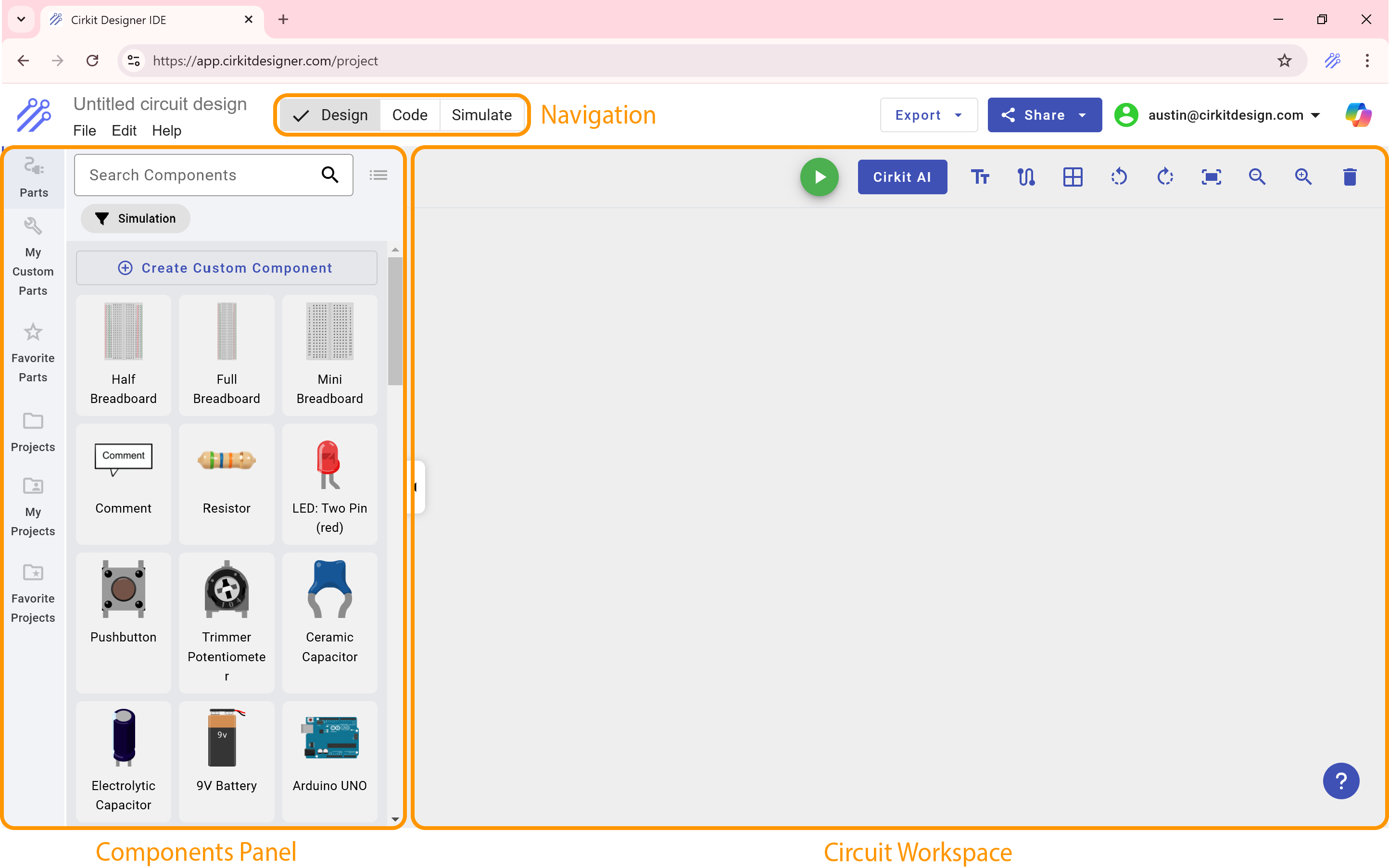
When you open Cirkit Designer, you’ll typically see:
- Components Panel: A list of parts you can drag onto your workspace.
- Circuit Workspace: The main area where you place and wire up components.
- Code Editor: Where you’ll write and edit Arduino code.
- Simulator: Tools for running and viewing the simulation of your circuit.
By default, the Components Panel and Circuit Workspace are visible right when you open the software. A top navigation lets you open the Code Editor and Simulator whenever you’re ready to write code or run a simulation. Having a basic understanding of these panels will help you follow the rest of this tutorial.
Step 1: Selecting Components
Finding Simulation-Compatible Parts
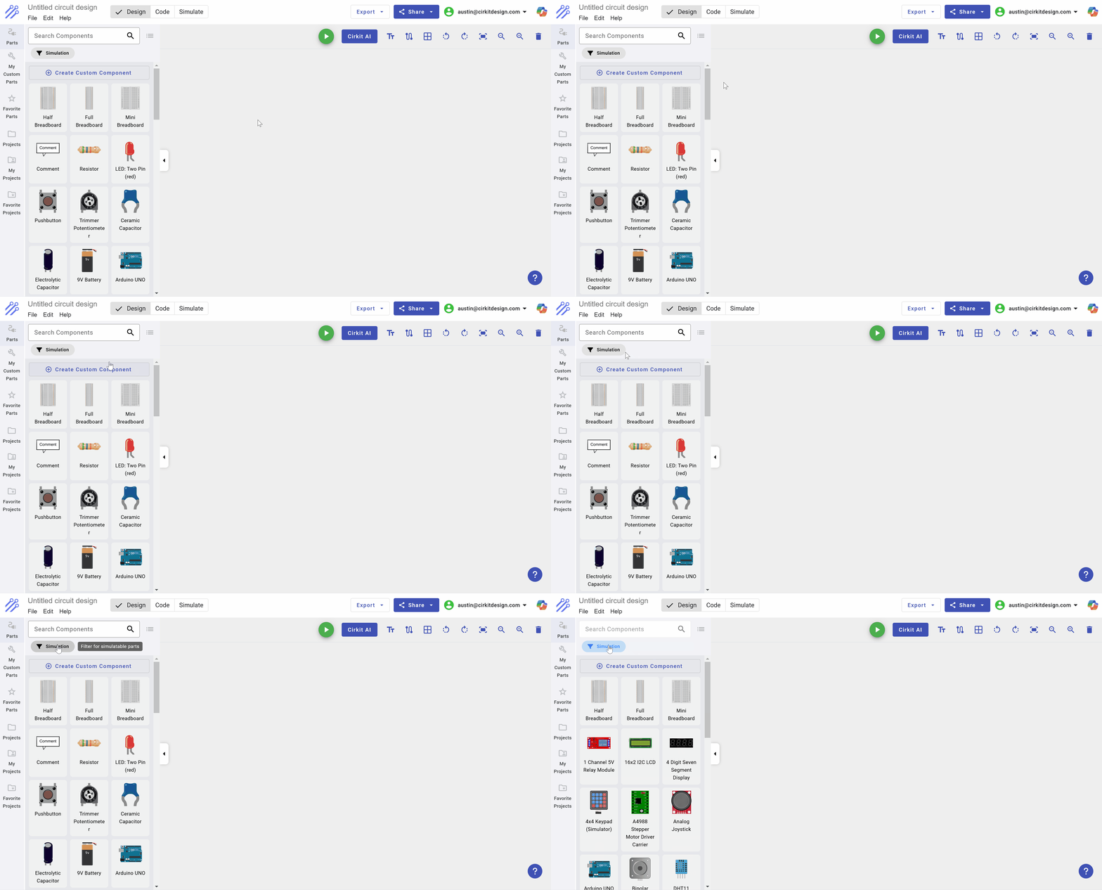
Not all components in the Cirkit Designer library are supported by the simulator. To find ones that are compatible:
- Go to the Components Panel.
- Click the Simulation Filter button so only supported components are displayed.
Adding electronic components
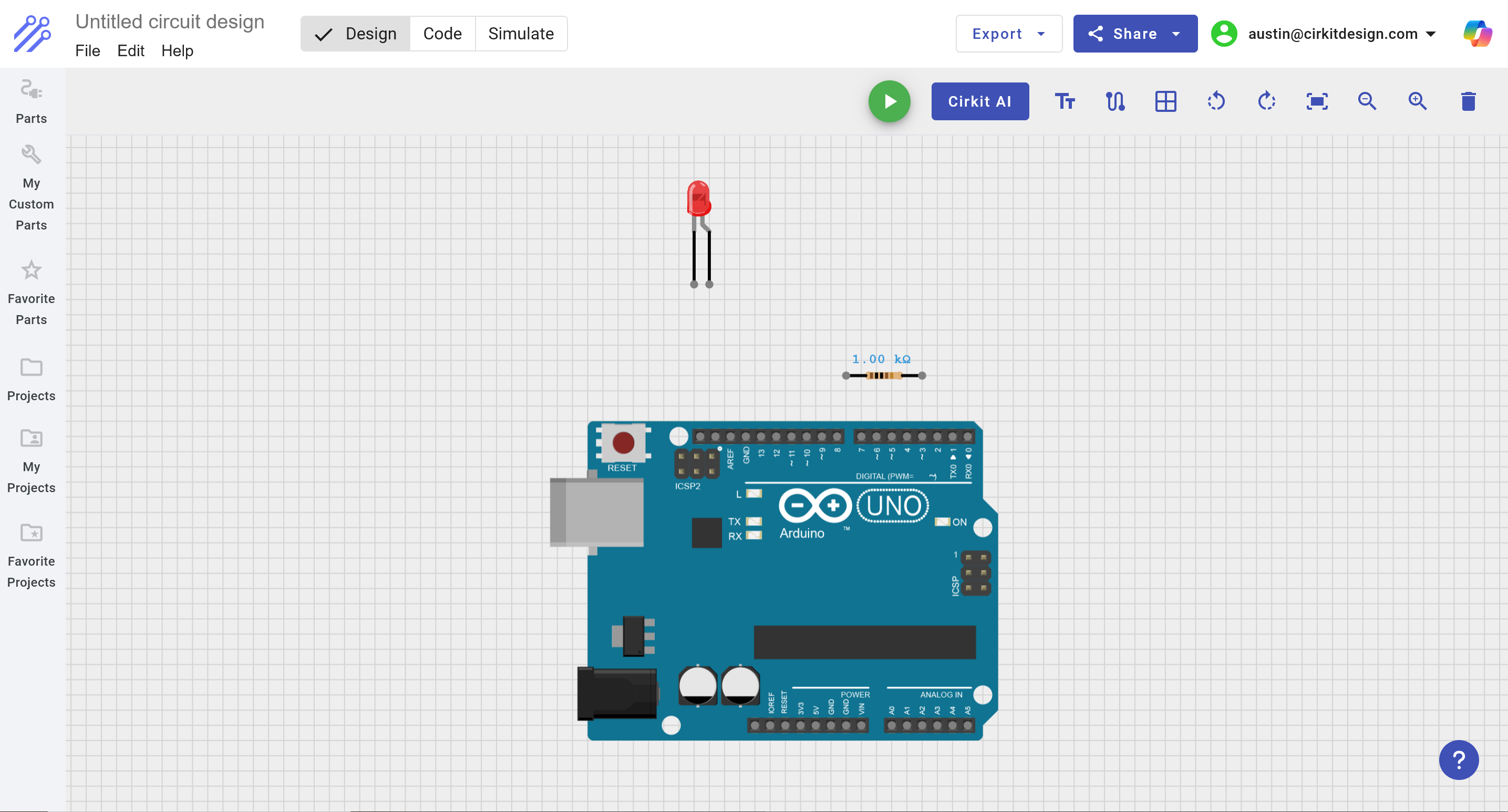
For this example, we’re going to create an LED blinker circuit using:
- Arduino UNO
- Red LED
- Resistor (1k Ω)
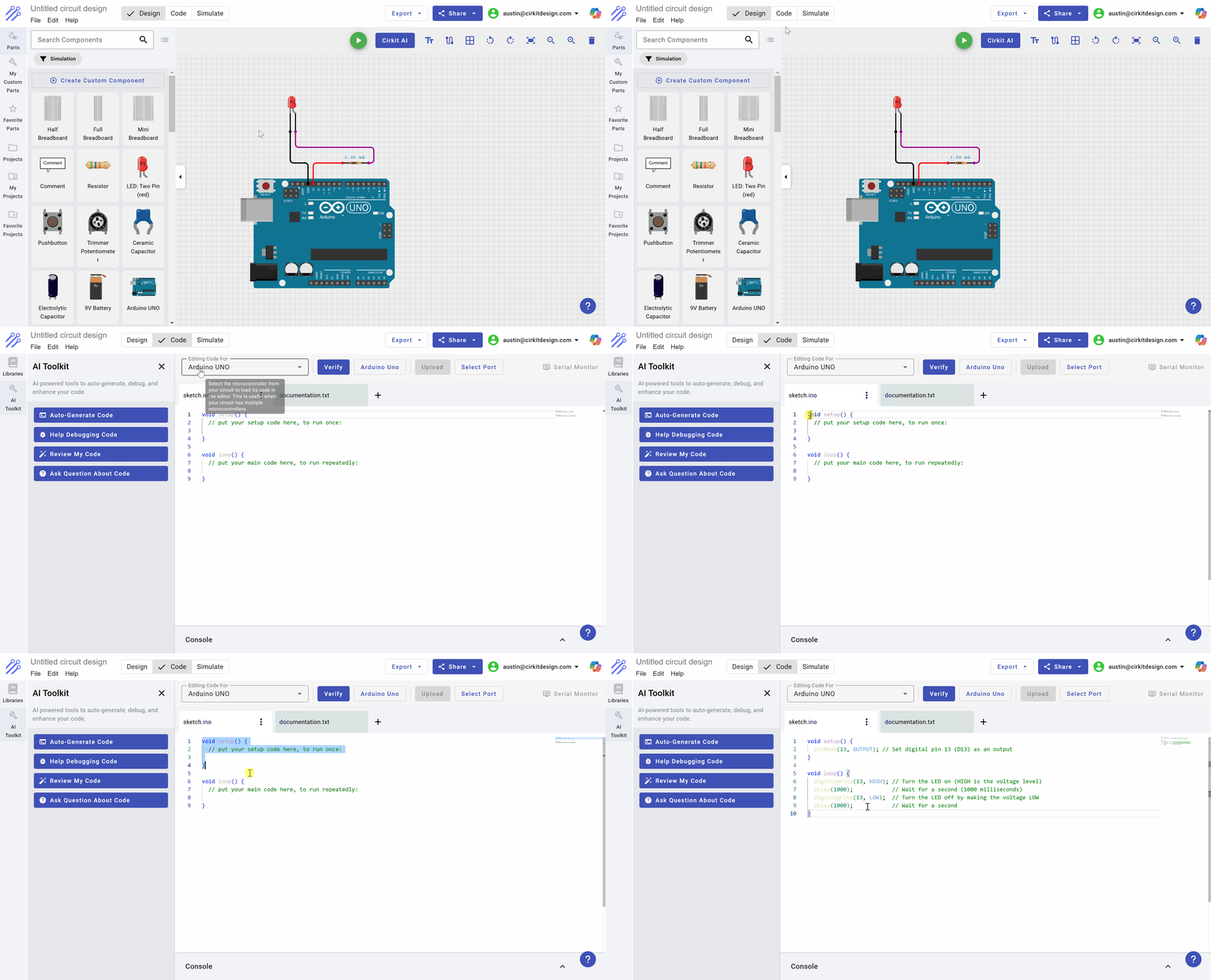
We'll proceed to add these parts to our circuit. After adding these parts, your circuit should look like this:
Wiring the components
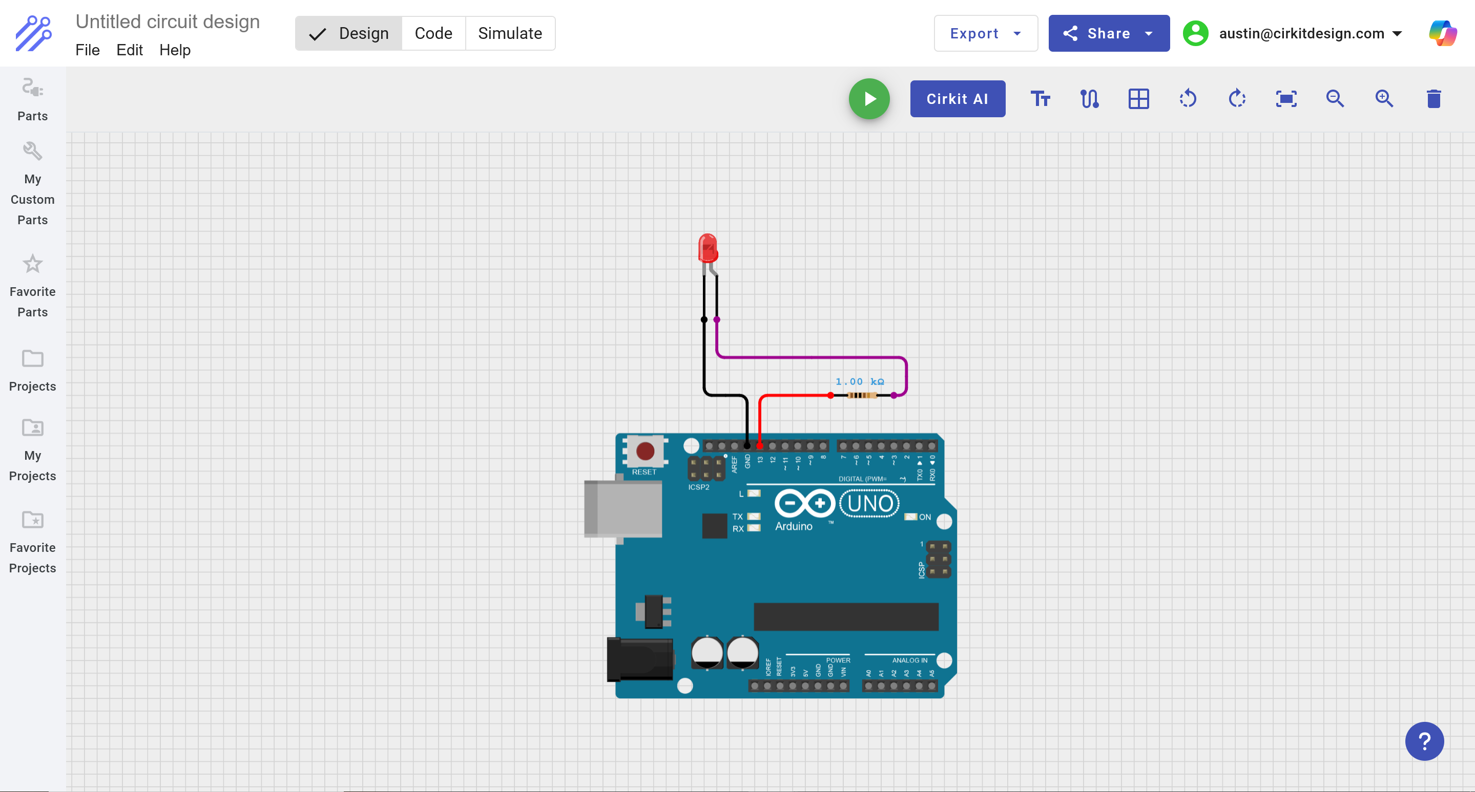
To make the LED blink, we'll use digital pin 13 on the Arduino to control the on/off state of the LED. To do so, we will place the following wires:
- D13 on the Arduino <-> Pin 1 on the resistor
- Pin 2 on the resistor <-> Anode of the LED
- Cathod of the LED <-> GND (ground) on the Arduino
After placing these wires, your wiring should look like this:
Step 2: Writing code to blink the LED
To control the LED, we’ll write a simple Arduino sketch that toggles pin 13 on and off:
- Open the Code Editor in Cirkit Designer.
- Paste the following code snippet:
void setup() {
  pinMode(13, OUTPUT); // Set digital pin 13 (D13) as an output
}

void loop() {
  digitalWrite(13, HIGH); // Turn the LED on (HIGH is the voltage level)
  delay(1000);            // Wait for a second (1000 milliseconds)
  digitalWrite(13, LOW);  // Turn the LED off by making the voltage LOW
  delay(1000);            // Wait for a second
}
Verifying code
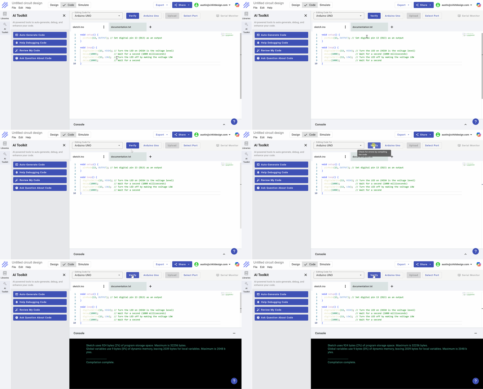
Click the Verify button to check for compilation errors. If you see “Compilation complete” in the console (in green), you’re ready to simulate!
Step 3: Running the simulation
To run the simulation, we'll first open the Simulator:
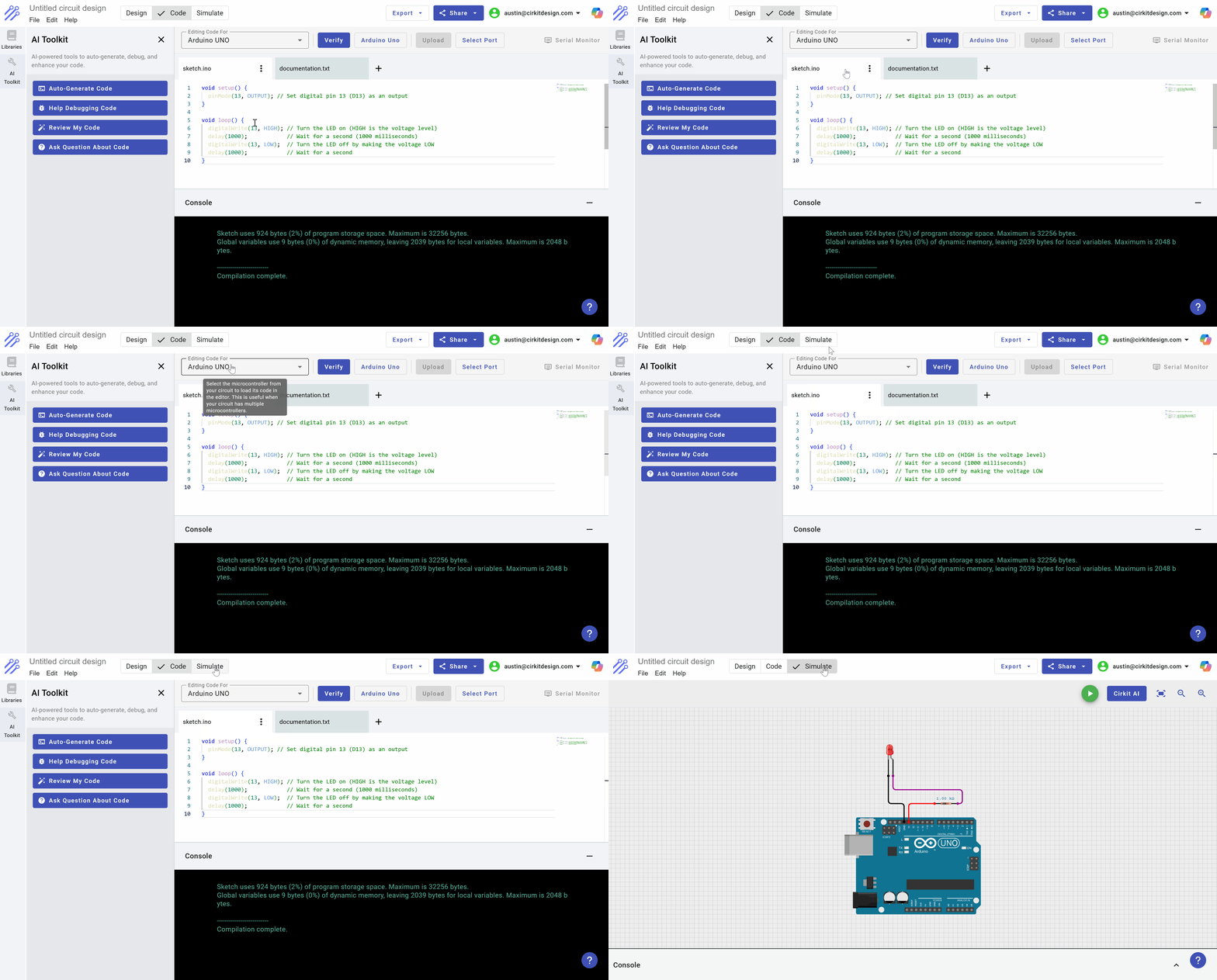
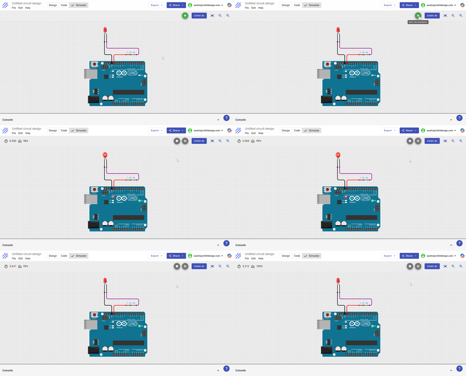
And then click the Play button to start the simulation.
If everything is wired and coded correctly, you should see the LED blink on and off with a one-second delay.
Conclusion
You’ve now seen the full process of creating a circuit, adding code, and running a simulation in Cirkit Designer. With this foundational knowledge, you’re ready to experiment with more advanced projects—have fun, and happy simulating!