
Control a Relay Module with an Arduino
 By Austin SmallUpdated November 13, 2026
Switch a 12 V solenoid on and off with an Arduino and a relay module, running in your browser before you build it. A relay is a switch worked by an electromagnet: a pin's small signal moves contacts that carry a circuit of their own, here the 12 V supply and the solenoid's 300 mA, far more than a pin can give. The Arduino never touches the 12 V.

Try it first, no parts needed
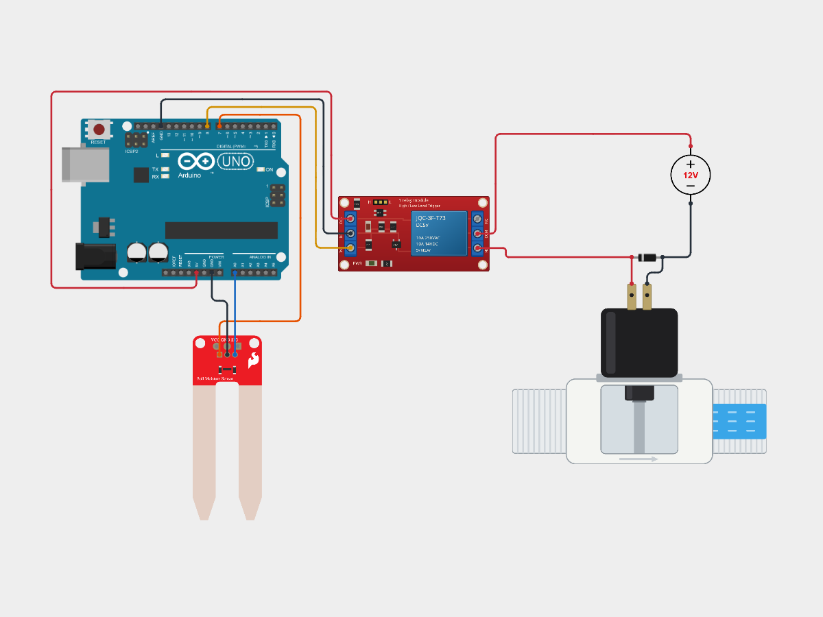
This is the whole project, wired and running in your browser. Press Run simulation: every three seconds the relay turns on for one, its red LED lights, and the solenoid's rod pulls in while the 12 V reaches it.

Arduino Uno serial monitor115200 baud
What the code does
The sketch turns the relay on for a second, then off for two, and says which on the Serial Monitor.
// A relay module switches a 12 V solenoid: on for 1 s, off for 2 s.
// Pin 7 drives the relay's IN; the relay's contacts switch the 12 V supply.
const int RELAY_PIN = 7;

void setup() {
  Serial.begin(115200);
  pinMode(RELAY_PIN, OUTPUT);
}

void loop() {
  digitalWrite(RELAY_PIN, HIGH);  // relay on: COM connects to NO
  Serial.println("Relay on");
  delay(1000);
  digitalWrite(RELAY_PIN, LOW);   // relay off: COM goes back to NC
  Serial.println("Relay off");
  delay(2000);
}const int RELAY_PIN = 7;The pin wired to the relay's IN. Any digital pin works; change the number to match your wiring.
pinMode(RELAY_PIN, OUTPUT);Makes pin 7 an output. Arduino pins start as inputs, which drive nothing, so until this line the relay stays off.
digitalWrite(RELAY_PIN, HIGH); // relay on: COM connects to NOPin 7 goes HIGH, 5 V. With the jumper on H, the relay turns on: you hear it click, its red LED lights, and COM joins NO, so the 12 V reaches the solenoid.
delay(1000);Keeps it on for a second. The solenoid in this circuit is rated for half its time on at most, so it rests longer than it works.
digitalWrite(RELAY_PIN, LOW); // relay off: COM goes back to NCPin 7 goes LOW: the relay turns off, COM goes back to NC, and the solenoid's spring pushes its rod out again.
delay(2000);Off for two seconds, then
loop()starts over. A relay is for switching now and then, not quickly: see limits.
Build it on an Arduino
Now with real parts. Check which terminal is which, wire it, get the code, then upload it and listen for the click. Using an ESP32 board? It has its own guide →
Which terminal is which: the relay module pinout
The module has two rows of screw terminals. On one side its inputs, which go to the Arduino: DC+, DC− and IN. On the other its contacts, which switch your load: NC, COM and NO. Modules differ, so wire yours by the labels printed beside its terminals or pins.

| Switches | One changeover switch: COM to NC while off, to NO while on |
|---|---|
| Inputs | DC+ and DC− (5 V), IN |
| Turns on | IN HIGH with the jumper on H; IN LOW on L |
| Coil | About 71 mA (SRD-05VDC-SL-C) from DC+, not from IN |
| Contacts | SRD-05VDC-SL-C: 7 A at 28 V DC resistive, 3 A inductive (Songle's L/R 7 ms test) |
| Speed | Up to 10 ms to switch on, 5 ms to switch off |
You'll need
- An Arduino Uno and its USB cable
- A 5 V relay module with an H/L jumper, set to H; screw terminals DC+, DC−, IN and NC, COM, NO
- A 12 V solenoid, such as Adafruit's small push-pull solenoid (product 412), and a 12 V DC supply that gives at least 300 mA
- A 1N4001 to 1N4007 diode
- Jumper wires, and a small screwdriver for the terminals
- Software to upload the sketch to the Uno: either Cirkit Designer, free in your browser, or the Arduino IDE, a free download for Windows, macOS and Linux
Wire it
Three wires from the module's inputs to the Uno, then the 12 V circuit through its contacts. Wire the 12 V side with the supply unplugged.
Tap a connection to see it on the circuit.
From Connect to Show Relay DC+ Uno 5V Show Relay DC− Uno GND Show Relay IN Uno pin 7 Show 12 V supply + Relay COM Show Relay NO Solenoid + Show Solenoid − 12 V supply − Show 1N4007 Across the solenoid, band on + Show The diode's band goes on the solenoid's + side. When the relay lets go, the solenoid's coil gives a kick; the diode gives it a path round the coil. Turned the other way, the diode conducts the 12 V straight back to the supply as soon as the relay turns on, a short circuit. The solenoid itself has no polarity: whichever lead you wire to NO is its + side.
Get the code
I'm using:Steps 2 and 3 follow the tool you pick.
The project opens with the sketch already in it. It needs no library.
No Arduino IDE yet? Download it free for Windows, macOS or Linux.
The sketch needs no library. Copy it into a new sketch:
How it works line by line is in what the code does, above.
Upload and check it
Plug in your Uno. In Cirkit, open the Build tab, then Upload firmware: click Select Port and pick your Uno, then Upload to Device. The first time, Cirkit asks you to install Cirkit Create Agent, a small desktop helper that lets it reach the board over USB. Then open Upload output and serial monitor and click Start Serial Monitor. Plug in the 12 V supply last.
Show me where to click in Cirkit
 Relay module on an Arduino UnoDesignCodeSimulateBuildShare
Select a device port
Select the device port for uploading code and serial communications
COM3 (Arduino Uno)- Open Build
- Choose Upload firmware
- Click Select Port
- Pick COM3 (Arduino Uno)
- Click Upload to Device
- Open Upload output and serial monitor
- Click Start Serial Monitor
In the Arduino IDE, choose Arduino Uno and its port from the board menu, press Upload, then open the Serial Monitor and set it to 115200 baud. Plug in the 12 V supply last.
Show me where to click in the Arduino IDE
relay_solenoid.ino// A relay module switches a 12 V solenoid: on for 1 s, off for 2 s. // Pin 7 drives the relay's IN; the relay's contacts switch the 12 V supply. const int RELAY_PIN = 7; void setup() { Serial.begin(115200);OutputSerial Monitor115200 baudCompiling sketch...
Sketch uses 2004 bytes (6%) of program storage space. Maximum is 32256 bytes.
Global variables use 206 bytes (10%) of dynamic memory, leaving 1842 bytes for local variables. Maximum is 2048 bytes.
Uploading...
Relay on
Relay off
Relay on
Relay off
Relay on
Done uploading.
- Click the board menu
- Pick Arduino Uno on COM3
- Click Upload
- Wait for Done uploading
- Click Serial Monitor
- Check it is set to 115200 baud
It works when:
- The module's green PWR LED is on as soon as the Uno has power.
- Every three seconds the relay clicks on for one second, its red LED lights, and the solenoid's rod pulls in; then it clicks off and the rod springs back.
- The Serial Monitor prints
Relay on, thenRelay off, in step with the clicks.
Device SerialRelay onRelay offRelay onRelay offRelay onOutputSerial MonitorRelay onRelay offRelay onRelay offRelay onNot working? If the relay doesn't click, see troubleshooting.
Troubleshooting
Find your symptom; the checks under it run from the most common cause down.
The relay doesn't click
If the Serial Monitor prints Relay on and Relay off, the Uno is running and the trouble is between it and the module. Check, in order:
- The green PWR LED is on. If not, DC+ isn't on 5V or DC− isn't on GND.
- IN is on pin 7, the pin in
RELAY_PIN. - The jumper is on H, or the sketch is reversed. On L the relay is on while IN is LOW: it clicks too, but in the other part of the loop.
The relay clicks, but the solenoid doesn't move
- The solenoid is on NO, not NC. On NC it gets 12 V while the relay is off, the opposite of the sketch, and none while it's on.
- The supply's + is on COM and its − reaches the solenoid's other lead.
- The supply gives 12 V and at least 300 mA. At a lower voltage a solenoid pulls weakly or not at all.
- The diode's band is on the solenoid's + side. The wrong way round, it shorts the supply while the relay is on.
It's on when it should be off
- The jumper is on L. Move it to H, or swap
HIGHandLOWin the sketch. - The load is on NC. NC is joined to COM while the relay is off; move it to NO.
- Your module has no jumper and switches on when IN is LOW. Many three-pin modules do: swap
HIGHandLOWin the sketch.
Nothing in the Serial Monitor, or garbled characters
- The Serial Monitor is set to 115200 baud. It must match
Serial.begin(115200)in the sketch.
How the relay module works
Inside the blue case is a coil and a springy switch. With no current in the coil, the spring holds the switch's common contact, COM, against NC. Current through the coil makes it an electromagnet, which pulls the switch over: COM leaves NC and joins NO. That move is the click you hear. When the current stops, the spring pulls it back.

On a module like this one, as K6JCA traced it, the coil's 71 mA comes from DC+, more than you should take from a pin: the module feeds it through a transistor; IN only lights the LED of an optocoupler, which switches that transistor with light. The jumper decides where the LED's other end goes: to DC− on H, so a HIGH on IN lights it, or to DC+ on L, so a LOW does. A diode across the coil soaks up the kick it gives when it lets go.
The contacts are a separate circuit. They don't care what they switch, as long as it's within their rating: here the 12 V supply and the solenoid. That is also why the solenoid needs its own diode: it is a coil too, and the module's diode only guards the relay's coil, not your load. The figure under this follows the module in the running circuit.
- Across the input
- 5.0 V
- Coil
- Energized
5.0 V across the input from pin 7: the coil is energized, COM connects to NO, and the solenoid gets 12 V.
Limits
| 5 V relay module (Songle SRD-05VDC-SL-C) | |
|---|---|
| Contacts | One changeover switch: COM, NO, NC. For a resistive load 7 A at 28 V DC or 10 A at 125 V AC; for an inductive load, tested by Songle at L/R = 7 ms, 3 A at 28 V DC. These are the relay's own ratings: check your module's listing too |
| Coil | 5 V, 71.4 mA (70 Ω, 0.36 W) for the relay's coil alone; the module's LEDs and transistor add a little |
| Speed | Up to 10 ms to switch on and 5 ms to switch off |
| Switching rate | Up to 30 times a minute with a load on the contacts, 300 without: a relay can't dim or set a speed with PWM |
| This solenoid | Adafruit 412: 12 V, about 300 mA, on for at most half the time (1 s on, 1 s off) |
The ratings printed on a relay's case are its best case; the datasheet's figures for an inductive load are lower. Stay well inside them, and switch only low-voltage DC on a module like this unless you know how to wire mains safely.
Relay module or something else?
| Turns on | Pins | Choose it for | |
|---|---|---|---|
| 1-channel module with an H/L jumper (this guide) | IN HIGH on H, IN LOW on L | DC+, DC−, IN | Either kind of board, with the trigger you choose |
| 1-channel module, 3 pins | IN LOW | VCC, GND, IN | The same job, with the sketch's HIGH and LOW swapped |
| 2- or 4-channel module | Each IN LOW | GND, IN1 to IN4, VCC, and a JD-VCC jumper | Several loads; remove the jumper to power the coils from their own 5 V supply |
| Transistor or MOSFET | Gate or base HIGH | Your own circuit | DC loads only, with no moving contacts; Adafruit suggests a power transistor and a diode to drive this solenoid |
Relay module FAQ
What do NO, NC and COM mean?
They are the three contacts of the relay's switch. COM, common, is the one that moves. NC, normally closed, is joined to COM while the relay is off; NO, normally open, while it is on. Wire a load to NO to switch it on with the relay, or to NC to switch it off.
digitalWrite(RELAY_PIN, HIGH);  // on: COM joins NO, leaves NC
digitalWrite(RELAY_PIN, LOW);   // off: COM back on NC
Why does my relay turn on when the pin is LOW?
Your module is active LOW: the jumper is on L, or it has no jumper and turns on with IN LOW, as Handson Technology's three-pin modules do. Swap HIGH and LOW in the sketch, or move the jumper to H.
Do I need a diode across the solenoid?
Yes, for a coil you switch, such as a solenoid or a valve: when the current stops, the coil gives a kick, and the diode, band on the + side, gives it a path round the coil. Adafruit says to use one with this solenoid and with its water valve. The module's own diode is across its relay's coil, not your load.
Can I power the solenoid from the Arduino's 5V pin?
No. This solenoid is rated for 12 V and draws about 300 mA; it needs its own 12 V supply, which is what the relay is for. The Uno's 5V pin powers only the module: the relay's coil and its LEDs.
Can I dim a lamp or set a motor's speed with a relay?
No. A relay is on or off, takes up to 10 ms to switch on, and Songle rates it for 30 operations a minute with a load, far slower than PWM's hundreds of pulses a second.
Does the relay module work with an ESP32?
Yes, with the jumper on H, DC+ on the ESP32's 5V pin and IN on a GPIO. On L, a 3.3 V HIGH may not be enough to turn the relay off. The ESP32 guide shows the wiring.
Simulating the relay module in Cirkit Designer
Cirkit's relay module joins COM to NC while it is off and to NO while it is on, as a plain switch in the circuit, and needs 4 to 5.5 V between DC+ and DC−. Its input is the module's as K6JCA traced it: the optocoupler's LED and 1 kΩ between IN and DC− on H, or between DC+ and IN on L; the jumper is a setting in its properties. The relay pulls in once about 0.8 mA flows, 1.8 V across the input, and lets go under 0.3 mA, 1.3 V; in between it keeps its state. The contacts move 10 ms after it pulls in and 5 ms after it lets go. It is tested on the Arduino Uno and the classic ESP32.
Those pull-in and let-go points are typical values for the module's parts, not guarantees: a real module's optocoupler and transistor vary. It doesn't model the coil's current, contact bounce or resistance, AC, or the contacts' ratings. The solenoid pulls its rod in from 9 V and lets go under 1.2 V, and warns when it is on more than 60 % of the time; it doesn't model the kick its coil gives when switched off, so the diode does nothing you can see in the simulation.
References
- K6JCA: schematic of a 1-channel relay module with high/low trigger
- Songle SRD relay datasheet (SRD-05VDC-SL-C)
- Handson Technology: 1-channel 5 V relay module user guide
- Handson Technology: 4-channel 5 V relay module user guide
- Adafruit: small push-pull solenoid, 12 V (product 412)
- TAU0730TM-14 solenoid specification (Adafruit 412)
- Vishay 1N4001 to 1N4007 datasheet
- Microchip ATmega328P datasheet, DS40002061B (40 mA at most from an I/O pin)
- Arduino: digitalWrite()
- Arduino: digital pins (inputs until set as outputs)
- Arduino: analogWrite() (PWM frequencies)
- Arduino IDE 2: uploading a sketch