
Turn a Servo with a Knob on an ESP32
 By Austin SmallUpdated November 12, 2026
Turn a servo with a knob on an ESP32, with nearly the same code as on an Arduino. The library is ESP32Servo, the servo takes its power from the board's 5V pin, and the sketch reads the knob with analogReadMilliVolts(), because the ESP32's raw analog count isn't proportional to the voltage.
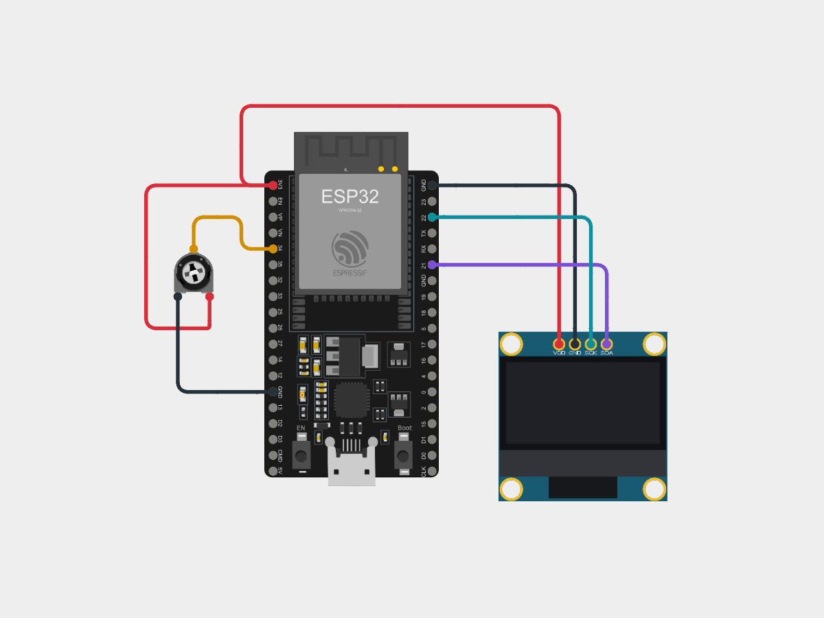
This guide uses an ESP32 DevKitC, the common ESP32-WROOM-32 board, with a micro servo on GPIO 13 and a knob on GPIO 34. On an ESP32-S3 the pins differ; see which pins work. For the servo itself, see the servo guide.
Try it first, no parts needed
This is the whole project, wired and running in your browser. Press Run simulation, then turn the knob and watch the horn follow it from 0° to 180°.

The knob on GPIO 34
Turning the knob from end to end swings the servo from 0° to 180°.
ESP32 serial monitor115200 baud
What the code does
The sketch reads the knob in millivolts, turns it into an angle from 0 to 180°, and turns the servo to it.
// Turn the knob on GPIO 34: the servo on GPIO 13
// follows it, from 0 to 180 degrees.
#include <ESP32Servo.h>

// GPIO 34 is on ADC1, which still reads while Wi-Fi runs.
const int KNOB_PIN = 34;
const int SERVO_PIN = 13;

Servo servo;
int shownAngle = -1;

void setup() {
  Serial.begin(115200);
  servo.setPeriodHertz(50);  // a pulse every 20 ms
  // Pulses from 544 us (0 degrees) to 2400 us (180).
  servo.attach(SERVO_PIN);
  // A 16-bit timer: pulse steps of 0.3 us, not 20 us.
  servo.setTimerWidth(16);
}

void loop() {
  // Millivolts, corrected with the chip's calibration.
  // The input's measurable range is about 150 to 3100 mV,
  // so that span is the servo's 0 to 180 degrees.
  int millivolts = analogReadMilliVolts(KNOB_PIN);
  int clamped = constrain(millivolts, 150, 3100);
  int angle = map(clamped, 150, 3100, 0, 180);
  servo.write(angle);

  // Print only when the angle changes.
  if (angle != shownAngle) {
    shownAngle = angle;
    Serial.print(F("IO34 "));
    Serial.print(millivolts);
    Serial.print(F(" mV angle="));
    Serial.println(angle);
  }
  delay(15);  // give the servo time to get there
}servo.setPeriodHertz(50); // a pulse every 20 msA pulse every 20 ms, 50 times a second, as on an Arduino.
servo.attach(SERVO_PIN);Starts the pulses on GPIO 13, with ESP32Servo's default range: 544 µs for 0° to 2400 µs for 180°.
servo.setTimerWidth(16);A 16-bit timer, so pulse lengths come in 0.3 µs steps. The default 10-bit timer steps by 19.5 µs, about 2° of the servo's travel. It comes after
attach(), which sets the timer up.int angle = map(clamped, 150, 3100, 0, 180);The knob's millivolts, held within 150 to 3100 mV, the input's documented measurable range, become 0 to 180°. See reading the knob.
servo.write(angle);Sets the pulse for that angle; the servo turns there and holds it.
Build it on an ESP32
Now with real parts. Wire it, get the code, then upload it and turn the knob. Not sure which wire is which? See the servo pinout.
You'll need
- An ESP32 DevKitC (ESP32-WROOM-32) and a USB cable that carries data
- A micro servo, such as the SG90
- A 10 kΩ potentiometer, the knob
- A breadboard and six jumper wires; three of them plug into the servo's connector
- Software to upload the sketch: either Cirkit Designer, free in your browser, or the Arduino IDE with Espressif's ESP32 boards installed
Wire it
Three wires for the servo, three for the knob.
Tap a connection to see it on the circuit.
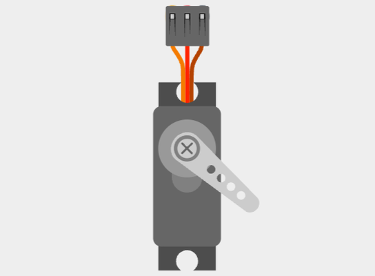
Pin Connect to the ESP32 Show Servo ground (brown) GND Show Servo power (red, middle) 5V Show Servo signal (orange) GPIO 13 Show Knob, one outer leg 3V3 Show Knob, middle leg GPIO 34 Show Knob, other outer leg GND Show The servo on 5V, the knob on 3V3. A hobby servo typically runs on 4.8 to 6 V, so it takes the board's 5V pin, which carries the USB's 5 V. The knob stays on 3V3: GPIO 34 isn't 5 V tolerant. The ESP32's 3.3 V signal is enough for a servo.
Get the code
I'm using:Steps 2 and 3 follow the tool you pick.
The project opens with the sketch and its library already in it, so there's nothing to install.
With the ESP32 boards installed (esp32 by Espressif, in the Boards Manager), open the Library Manager (1), search for ESP32Servo (2), and install it (3).
Then copy the sketch into a new one:
How it works line by line is in what the code does, above.
Upload and check it
Plug in your ESP32. In Cirkit, open the Build tab, then Upload firmware: click Select Port and pick your board, then Upload to Device. The first time, Cirkit asks you to install Cirkit Create Agent, a small desktop helper that lets it reach the board over USB. Then open Upload output and serial monitor and click Start Serial Monitor.
Show me where to click in Cirkit
 Servo on an ESP32DesignCodeSimulateBuildShare
Select a device port
Select the device port for uploading code and serial communications
COM4 (ESP32)- Open Build
- Choose Upload firmware
- Click Select Port
- Pick COM4 (ESP32)
- Click Upload to Device
- Open Upload output and serial monitor
- Click Start Serial Monitor
In the Arduino IDE, choose ESP32 Dev Module and its port from the board menu, press Upload, then open the Serial Monitor and set it to 115200 baud.
Show me where to click in the Arduino IDE
esp32_servo_knob.ino// Turn the knob on GPIO 34: the servo on GPIO 13 // follows it, from 0 to 180 degrees. #include <ESP32Servo.h> // GPIO 34 is on ADC1, which still reads while Wi-Fi runs. const int KNOB_PIN = 34;
OutputSerial Monitor115200 baudCompiling sketch...
Sketch uses 302947 bytes (23%) of program storage space. Maximum is 1310720 bytes.
Global variables use 21248 bytes (6%) of dynamic memory, leaving 306432 bytes for local variables. Maximum is 327680 bytes.
Uploading...
IO34 1660 mV angle=92
IO34 835 mV angle=41
IO34 3139 mV angle=180
IO34 142 mV angle=0
Done uploading.
- Click the board menu
- Pick ESP32 Dev Module on COM4
- Click Upload
- Wait for Done uploading
- Click Serial Monitor
- Check it is set to 115200 baud
It works when:
- The horn follows the knob, from one end of its travel to the other.
- After a few start-up lines from the ESP32's boot ROM, the Serial Monitor prints a line each time the angle changes, such as
IO34 835 mV angle=41with the knob a quarter of the way round, as pictured. On real hardware the millivolts, and so the angles, vary a little.
With the knob a quarter of the way round, GPIO 34 reads 835 mV and the sketch writes 41°. Device SerialIO34 1660 mV angle=92IO34 835 mV angle=41IO34 3139 mV angle=180IO34 142 mV angle=0OutputSerial MonitorIO34 1660 mV angle=92IO34 835 mV angle=41IO34 3139 mV angle=180IO34 142 mV angle=0Not working? See troubleshooting.
Which ESP32 pins work for the servo and the knob
The servo's signal needs a pin that ESP32Servo accepts: its attach() refuses any other. The knob needs a pin on ADC1, the analog input that keeps working while Wi-Fi runs. GPIO 13 and 34 are both fine on a classic ESP32.
| Classic ESP32 | ESP32-S3 | |
|---|---|---|
| Servo signal (ESP32Servo 3.2.1) | GPIO 4, 13, 14, 16 to 19, 21 to 23, 25 to 27, 32 and 33; also 2, 5, 12 and 15, but they are strapping pins | GPIO 1 to 21, 35 to 45, 47 and 48 |
| Knob (ADC1) | GPIO 32 to 39; on the DevKitC, 32 to 35, 36 (VP) and 39 (VN) | GPIO 1 to 10 |
| Avoid for the servo: input-only | GPIO 34 to 39, fine for the knob | None |
| Avoid: flash | GPIO 6 to 11 | GPIO 26 to 32, and 33 to 37 on modules with octal flash or octal PSRAM |
| Avoid: boot (strapping) | GPIO 0, 2, 5, 12 and 15 | GPIO 0, 3, 45 and 46 |
To move the servo, change the pin the sketch attaches to:
// The servo on GPIO 25 instead of 13.
const int SERVO_PIN = 25;
Reading the knob
The ESP32's analog input gives 12 bits, 0 to 4095, but the count isn't proportional to the voltage, and at the Arduino core's default attenuation, 11 dB, the classic ESP32 measures only from about 150 mV to 3,100 mV. So the sketch reads millivolts with analogReadMilliVolts() and treats 150 to 3,100 mV as the knob's whole travel: below and above it the reading hardly changes, so the ends would otherwise never reach 0° or 180°.
Troubleshooting
Find your symptom; the checks under it run from the most common cause down.
The servo doesn't move, but the Serial Monitor shows readings
The sketch runs, but its pulses don't reach the servo, or the servo has no power. Check, in order:
- The signal wire is on GPIO 13. It must be the pin
servo.attach()names, and one ESP32Servo accepts; see which pins work. - The servo's power is on 5V, not 3V3. 3.3 V is below the servo's 4.8 to 6 V.
- With a separate supply, the grounds are joined. Join the supply's ground to the ESP32's GND.
The board resets with "Brownout detector was triggered"
The servo pulled the supply's voltage down, and the ESP32 reset itself to stay safe.
- Only one small servo runs from the board's 5V. Give a bigger servo, or a second one, its own 5 to 6 V supply, with its ground joined to the ESP32's GND.
- The USB port or cable is up to it. A hub or a long, thin cable sags under load; try a port on the computer itself.
The servo moves in small jumps
setTimerWidth(16)comes afterattach(). Before it, the timer stays at 10 bits, about 2° a step.
Nothing in the Serial Monitor, or garbled characters
- The Serial Monitor is set to 115200 baud. It must match
Serial.begin(115200)in the sketch. The ESP32's own start-up lines, from its boot ROM, come first at the same speed, so they should be readable too. - The sketch prints only when the angle changes. It prints once at the start; turn the knob to see more.
Compiling fails: 'SOC_LEDC_TIMER_BIT_WIDE_NUM' was not declared
'SOC_LEDC_TIMER_BIT_WIDE_NUM' was not declared- The sketch includes Arduino's
Servo.h. Version 1.3.0 of that library doesn't compile for the ESP32 boards' current release, 3.3.5. Include<ESP32Servo.h>instead, as this guide's sketch does; the rest of the code stays the same.
Compiling fails: ESP32Servo.h: No such file or directory
ESP32Servo.h: No such file or directory- ESP32Servo is installed. In the Arduino IDE, install it from the Library Manager, as in step 2 of building it. In Cirkit the project already has it.
No port appears for the ESP32
- The cable carries data. The board's USB port carries its serial link as well as power, so a cable that only charges powers the board but shows no port.
- The board's USB-to-serial chip has its driver. Its name, such as CP210x, is printed on the chip near the USB socket. The driver usually installs itself; if no port appears, install it from the chip's maker (Silicon Labs for a CP210x).
The upload stops at Connecting..., then says Failed to connect
Connecting..., then says Failed to connect- The board is in download mode. Hold BOOT, press and release EN (RST on some boards), then release BOOT, and upload again.
More causes are in the servo guide's troubleshooting.
FAQ
Can I power the servo from the ESP32's 3V3 pin?
No. 3.3 V is below a hobby servo's usual 4.8 to 6 V. Use the 5V pin for one small servo, or a separate supply.
Does the same code work on an ESP32-S3 or an ESP32-C3?
Yes, with a few changes. Move the knob to an ADC1 pin, GPIO 1 on either, and set KNOB_PIN to 1. Put the servo on a pin ESP32Servo accepts: GPIO 13 works on the S3; on the C3 use one of 0 to 10 or 18 to 21. On a C3, ESP32Servo's timer goes up to 14 bits, so use setTimerWidth(14), and its input measures 0 to 2500 mV, so change 150 and 3100 to 0 and 2500 in the two lines that clamp and map the reading. The S3's input measures from 0 mV, so there change 150 to 0.
Can I use the Arduino Servo library on an ESP32?
Not with the ESP32 boards' current release: Servo 1.3.0 fails to compile for esp32 3.3.5; see the compile error. ESP32Servo gives you the same Servo class, with attach(), write() and read(), so code written for the Arduino library needs only the other include.
How do I control several servos?
Make a Servo object for each and attach each to its own pin, each with its own setTimerWidth(16) after attach(). Give them their own supply.
Simulating the servo on an ESP32 in Cirkit Designer
Cirkit runs your compiled sketch on an emulated ESP32, and its servo measures the pulses on GPIO 13 as in the servo guide; the servo is tested on the classic ESP32, the ESP32-S3 and the Arduino Uno. The ESP32's analog input follows Espressif's default calibration curve, and the knob adds no noise. The horn reaches its angle at once, with no speed, torque or current, so a supply that would sag on hardware never does here.
References
- Espressif esptool: troubleshooting (download mode by hand, the boot log at 115200 baud)
- ESP-IDF: establishing a serial connection (the USB-to-UART bridge and its driver)
- ESP32Servo library, version 3.2.1 (default range, setPeriodHertz(), setTimerWidth() and its limits)
- Arduino-ESP32 core, version 3.3.5 (the ADC's default 11 dB attenuation)
- Arduino-ESP32: ADC, including analogReadMilliVolts() and the measurable range
- ESP-IDF: ADC on the ESP32, and ADC2 shared with Wi-Fi
- ESP-IDF: fatal errors, including the brownout detector's message
- Espressif ESP32-DevKitC user guide (its pins, including 5V)
- Espressif ESP32 datasheet
- Espressif ESP32-S3 datasheet
- ESP-IDF: GPIO on the ESP32-S3 (flash and octal memory pins)
- Pololu: the servo control interface in detail (3.3 V and 5 V signals)
- Pololu: electrical characteristics of servos (4.8 to 6 V)