
Blink an LED with an Arduino
 By Austin SmallUpdated November 11, 2026
Blink an LED with an Arduino: on for a second, off for a second. It's Arduino's own first example, and here it runs in your browser before you build it. An LED lights only one way round, and it always needs a resistor in series to limit its current.

Try it first, no parts needed
This is the whole project, wired and running: an LED on pin 9 through a 220 Ω resistor. Press Run simulation. The LED turns on for a second and off for a second, and the Serial Monitor prints LED on and LED off.

The LED, blinking
Its glow, enlarged.
Lights up when the simulation runs.
Arduino Uno serial monitor115200 baud
What the code does
The sketch switches pin 9 on, waits a second, switches it off, waits a second, and repeats.
// Blink: the LED on pin 9 on for a second, off for a
// second, and the Serial Monitor says which.
const int LED_PIN = 9;  // a PWM pin: marked ~ on the Uno

void setup() {
  Serial.begin(115200);
  pinMode(LED_PIN, OUTPUT);
}

void loop() {
  digitalWrite(LED_PIN, HIGH);  // on
  Serial.println("LED on");
  delay(1000);
  digitalWrite(LED_PIN, LOW);   // off
  Serial.println("LED off");
  delay(1000);
}const int LED_PIN = 9; // a PWM pin: marked ~ on the UnoThe LED is on pin 9. Any digital pin can blink it; pin 9 can also dim it, as in dim it with a knob.
pinMode(LED_PIN, OUTPUT);Makes pin 9 an output, so the sketch can switch it between 0 V and 5 V.
digitalWrite(LED_PIN, HIGH); // onPin 9 to 5 V: current flows through the resistor and the LED, and it lights.
delay(1000)then waits a second.Serial.println("LED on");Says so on the Serial Monitor, so you can follow it without watching the LED.
digitalWrite(LED_PIN, LOW); // offPin 9 to 0 V: no current, so the LED goes dark for another second, and
loop()starts again.
Build it on an Arduino
Now with real parts: check which leg is which, wire it, get the code, then upload it and watch it blink. Using an ESP32 board? It has its own guide →
Which leg is which: the LED pinout
An LED has two leads. The longer one is the anode (+): it goes to the Arduino pin, through the resistor. The shorter one is the cathode (−): it goes to GND. Wired the other way round, the LED stays dark. If the legs have been trimmed, look at the rim at the bottom of the lens: it is flat on the cathode's side.

| Leads | Two: the anode (+, the long leg) and the cathode (−, the short leg) |
|---|---|
| Lights when | Current flows from anode to cathode |
| Forward voltage | 1.9 V typical, 2.3 V max, at 10 mA (Kingbright WP7113ID, a 5 mm red LED) |
| Current | 30 mA max for the WP7113ID; 220 Ω from a 5 V pin gives about 14 mA |
| Brightness | analogWrite(pin, 0 to 255) on a PWM pin, marked ~ on the Uno |
| Library | None: digitalWrite() and analogWrite() are built in |
You'll need
- An Arduino Uno (a Nano works the same way) and its USB cable
- A red LED, 5 mm or 3 mm
- A 220 Ω resistor (red, red, brown bands)
- A breadboard and two jumper wires
- No LED to hand? Blink works on the Uno's built-in LED too: use
LED_BUILTIN, pin 13, instead of pin 9 - Software to upload the sketch to the Uno: either Cirkit Designer, free in your browser, or the Arduino IDE, a free download for Windows, macOS and Linux
Wire it
The LED and its resistor in a row from pin 9 to GND: two wires.
Tap a connection to see it on the circuit.
Pin Connect to the Uno Show LED anode (long leg) 220 Ω resistor, then pin 9 Show LED cathode (short leg) GND Show The resistor can go on either side of the LED, as long as the two are in series between pin 9 and GND. From a 5 V pin, anything from 220 Ω to 1 kΩ works: the bigger the resistor, the dimmer the LED.
Get the code
I'm using:Steps 2 and 3 follow the tool you pick.
The project opens with the sketch already in it, so there's nothing to install.
No Arduino IDE yet? Download it free for Windows, macOS or Linux.
The sketch needs no library. Copy it into a new sketch:
How it works line by line is in what the code does, above.
Upload and check it
Plug in your Uno. In Cirkit, open the Build tab, then Upload firmware: click Select Port and pick your Uno, then Upload to Device. The first time, Cirkit asks you to install Cirkit Create Agent, a small desktop helper that lets it reach the board over USB. Then open Upload output and serial monitor and click Start Serial Monitor.
Show me where to click in Cirkit
 Blink on an Arduino UnoDesignCodeSimulateBuildShare
Select a device port
Select the device port for uploading code and serial communications
COM3 (Arduino Uno)- Open Build
- Choose Upload firmware
- Click Select Port
- Pick COM3 (Arduino Uno)
- Click Upload to Device
- Open Upload output and serial monitor
- Click Start Serial Monitor
In the Arduino IDE, choose Arduino Uno and its port from the board menu, press Upload, then open the Serial Monitor and set it to 115200 baud.
Show me where to click in the Arduino IDE
blink_led.ino// Blink: the LED on pin 9 on for a second, off for a // second, and the Serial Monitor says which. const int LED_PIN = 9; // a PWM pin: marked ~ on the Uno void setup() { Serial.begin(115200);OutputSerial Monitor115200 baudCompiling sketch...
Sketch uses 1992 bytes (6%) of program storage space. Maximum is 32256 bytes.
Global variables use 202 bytes (9%) of dynamic memory, leaving 1846 bytes for local variables. Maximum is 2048 bytes.
Uploading...
LED on
LED off
LED on
LED off
Done uploading.
- Click the board menu
- Pick Arduino Uno on COM3
- Click Upload
- Wait for Done uploading
- Click Serial Monitor
- Check it is set to 115200 baud
It works when:
- The LED blinks, on for a second and off for a second.
- The Serial Monitor prints
LED onandLED offin step with the LED.
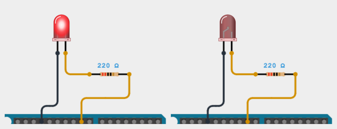
Left: pin 9 HIGH and the LED lit. Right: a second later, pin 9 LOW and the LED dark. Device SerialLED onLED offLED onLED offOutputSerial MonitorLED onLED offLED onLED offNot working? See troubleshooting.
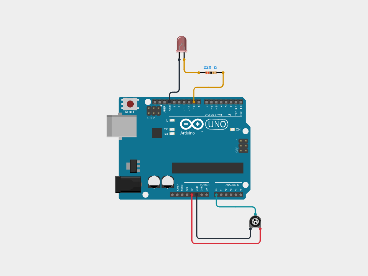

Troubleshooting
Find your symptom; the checks under it run from the most common cause down.
The LED doesn't light, but the Serial Monitor prints LED on and LED off
The sketch runs, but no current flows through the LED. Check, in order:
- The LED is the right way round. The long leg goes toward pin 9, the short leg, on the flat side of the rim, to GND. Backwards, it stays dark; turn it round.
- The circuit is complete. Pin 9, the resistor, the LED and GND form one loop: on a breadboard, the resistor and the LED share a row, and nothing else sits in that row.
- The wire is on pin 9. It must be the pin the sketch names.
The LED lights, but only faintly
- The pin is set as an output. With
digitalWrite()and nopinMode(LED_PIN, OUTPUT), HIGH only turns on the pin's internal pull-up resistor, which lights an LED faintly. - The resistor is 220 Ω to 1 kΩ. Bands red, red, brown are 220 Ω; brown, black, red are 1 kΩ. 10 kΩ (brown, black, orange) lets through only about 0.3 mA, too little to see well.
Nothing in the Serial Monitor, or garbled characters
- The Serial Monitor is set to 115200 baud. It must match
Serial.begin(115200)in the sketch. - The sketch prints a line a second. If nothing comes, check the board and port chosen for the upload.
How an LED works
An LED is a diode that gives out light: current flows one way only, from anode to cathode, and while it flows, the LED lights. A red LED needs about 2 V across it to light. Past that, its current climbs steeply, and without a resistor it would draw as much as the pin can give. The resistor limits the current. It takes the rest of the 5 V, and its value sets the current.


To pick a resistor for another LED or board: subtract the LED's forward voltage from the pin's voltage and divide by the current you want. For 10 mA from a 5 V pin: (5 − 1.9) ÷ 0.010 = 310 Ω, so 330 Ω.
Current, brightness and other limits
These are the limits that decide what you can wire, for a common 5 mm red LED on an Uno.
| The Kingbright WP7113ID, a 5 mm red LED, at 25 °C, on an Uno | |
|---|---|
| Current | 30 mA at most for the LED, continuously. 220 Ω from 5 V gives about 14 mA. |
| Uno pin | Rated at 20 mA. 40 mA is its absolute maximum, past which the chip can be damaged. |
| Uno, all pins | 200 mA at most through the chip's supply pins, and no more than 150 mA sourced from each of its two groups of pins. |
| Forward voltage | 1.9 V typical, 2.3 V at most, at 10 mA. Other colours can need more: the green and blue of an RGB LED such as the Fedy FD-5WSRGB-A, 3.2 V typical. |
| Reverse voltage | 5 V at most: see the pinout. |
| Light | About 50 mcd at 10 mA, in a narrow 30° beam: brightest seen head on. |
Other LEDs have their own limits, so check your LED's datasheet. Keep each at about 9 to 14 mA, which 330 Ω to 220 Ω gives from 5 V, and add up the LEDs that are on at once: ten at 14 mA is 140 mA, close to the 150 mA one group of pins can supply. For more LEDs, or brighter ones, let a transistor switch them from the 5 V supply, so the pin only drives the transistor.
Which LED, or something else?
An LED and a resistor is the simplest light; for colour, a strip or more current, pick one of these.
| Wiring | Can dim | Choose it for | |
|---|---|---|---|
| The Uno's built-in LED | None: on pin 13, LED_BUILTIN | No: pin 13 has no PWM | Checking a board and an upload work |
| One LED and a resistor | Two parts, two wires: this guide | Yes, on a PWM pin: dim it with a knob | Indicators, status lights, your first circuit |
| RGB LED | Four leads, three resistors, three PWM pins | Each colour, to mix any colour | A status light in any colour: the RGB guide |
| Addressable LEDs (WS2812B, NeoPixel) | One data pin for a whole chain, and a 5 V supply | Each LED, any colour, through a library | Strips and rings: many colours from one pin |
| A transistor and a brighter LED or strip | The pin drives the transistor; the supply drives the LEDs | Yes, with PWM on the transistor | More current than a pin's 20 mA |
For one light, or a few, an LED and a resistor on a pin is all you need.
LED FAQ
Which leg of an LED is positive?
The longer leg, the anode, is positive: it goes toward the Arduino pin, through the resistor. The shorter leg, the cathode, goes to GND. With the legs cut, look at the rim at the bottom of the lens: it is flat on the cathode's side. See the pinout.
Can I connect an LED without a resistor?
No: nothing would limit the current, and the LED or the pin can be damaged. Always put a resistor in series; 220 Ω is safe for a red LED on a 5 V Uno.
What resistor does an LED need?
(Supply voltage − LED forward voltage) ÷ current. For a red LED at about 14 mA from 5 V, 220 Ω; for 10 mA, 330 Ω. Anything up to 1 kΩ still lights a red LED visibly on a 5 V board, just dimmer. See how an LED works.
How do I change an LED's brightness?
Put it on a PWM pin (3, 5, 6, 9, 10 or 11 on an Uno) and use analogWrite(pin, 0 to 255) instead of digitalWrite(). Dim it with a knob runs it live.
How many LEDs can an Arduino drive?
About ten at 14 mA each, one per pin with its own resistor. The chip can supply 150 mA from each of its two groups of pins and 200 mA in all, and that 200 mA also carries the chip's own current. A pin is rated at 20 mA, so one LED at about 14 mA is within it. For more, use a transistor or addressable LEDs; see the limits.
Simulating the LED in Cirkit Designer
Cirkit's red LED lights when its anode is at least 2 V above its cathode, so it stays dark backwards and lights from a 3.3 V or 5 V pin. Its brightness updates every 20 ms: a blink shows as on and off, and a PWM signal as the share of each pulse it's lit, a steady partial brightness, as on a real LED. It is tested on the Arduino Uno, the ESP32-S3 and the classic ESP32.
Where it differs from a real LED: Cirkit works with voltages, not current, so the resistor's value doesn't change the brightness, and an LED with no resistor still lights instead of overheating. On real hardware, always fit the resistor.
References
- Kingbright WP7113ID, 5 mm red LED: datasheet (forward voltage, current, reverse voltage, intensity, leads, the flat on the cathode side, 2.54 mm lead spacing, the current against voltage curve)
- Arduino: analogWrite() (PWM pins, 490 and 980 Hz, 0 to 255)
- Arduino: Blink (the simplest example; HIGH and LOW, a second each; LED_BUILTIN on pin 13; the anode and cathode; 220 Ω, visible up to 1 kΩ)
- Arduino Nano (the same ATmega328P and pins as the Uno)
- Kingbright WP710A10ID, 3 mm red LED: datasheet (two leads, the cathode shorter)
- SparkFun: resistors (the colour code)
- Arduino IDE 2: uploading a sketch (the board menu, Upload, the Serial Monitor)
- Arduino: digital pins (the pull-up dimly lighting an LED)
- Microchip ATmega328P datasheet (absolute maximum ratings: 40 mA per pin, 200 mA in all; pins rated at 20 mA; 150 mA per group)
- Worldsemi WS2812B datasheet (addressable LEDs on one data line)
- Arduino AVR core 1.8.6: analogWrite() on a pin without PWM
- Fedy FD-5WSRGB-A, 5 mm RGB LED: datasheet (green and blue forward voltage)
- SparkFun: light-emitting diodes (polarity, why the resistor)