
An RGB LED Colour Wheel on an Arduino
 By Austin SmallUpdated November 11, 2026
Turn a knob and an RGB LED goes round the colour wheel: red, yellow, green, cyan, blue, magenta and back to red. An RGB LED is three LEDs in one lens, red, green and blue, sharing one lead. Set each one's brightness with analogWrite(), and their light mixes.
This guide uses the common-cathode kind, whose shared lead goes to GND; the common-anode kind is under make it yours. If you haven't used an LED with an Arduino before, the LED guide covers one on its own.
Try it first, no parts needed
This is the whole project, wired and running in your browser. Press Run simulation, then turn the knob and watch the LED go round the colour wheel.

The knob on A0
Turning the knob from end to end goes once round the colour wheel.
The RGB LED
Its colour, enlarged: three PWM levels mixed.
Lights up when the simulation runs.
Arduino Uno serial monitor115200 baud
What the code does
The sketch reads the knob, turns its position into a hue on the colour wheel, and sets each colour's level to mix it.
// Turn the knob on A0: the RGB LED runs round the colour
// wheel, red, yellow, green, cyan, blue, magenta, red.
const int KNOB_PIN = A0;
const int RED_PIN = 11;  // PWM pins: marked ~ on the Uno
const int GREEN_PIN = 10;
const int BLUE_PIN = 9;

int shownHue = -1;

void setup() {
  Serial.begin(115200);
}

// Each 60 degrees of hue, one colour fades in or out.
void showHue(int hue) {
  int rising = map(hue % 60, 0, 59, 0, 255);
  int falling = 255 - rising;
  int red = 0;
  int green = 0;
  int blue = 0;
  switch (hue / 60) {
    case 0: red = 255; green = rising; break;   // to yellow
    case 1: red = falling; green = 255; break;  // to green
    case 2: green = 255; blue = rising; break;  // to cyan
    case 3: green = falling; blue = 255; break; // to blue
    case 4: red = rising; blue = 255; break;    // to magenta
    default: red = 255; blue = falling; break;  // to red
  }
  analogWrite(RED_PIN, red);
  analogWrite(GREEN_PIN, green);
  analogWrite(BLUE_PIN, blue);

  Serial.print(F("hue="));
  Serial.print(hue);
  Serial.print(F(" R="));
  Serial.print(red);
  Serial.print(F(" G="));
  Serial.print(green);
  Serial.print(F(" B="));
  Serial.println(blue);
}

void loop() {
  int reading = analogRead(KNOB_PIN);  // 0 to 1023
  int hue = map(reading, 0, 1023, 0, 359);
  if (hue != shownHue) {
    shownHue = hue;
    showHue(hue);
  }
  delay(10);
}const int RED_PIN = 11; // PWM pins: marked ~ on the UnoOne PWM pin for each colour: red on 11, green on 10, blue on 9.
int hue = map(reading, 0, 1023, 0, 359);The knob's reading becomes a hue: a position on the colour wheel, 0 to 359 degrees.
int rising = map(hue % 60, 0, 59, 0, 255);How far the hue is through its sixth of the wheel, as a level from 0 to 255;
fallingis the same from the other end.switch (hue / 60) { case 0: red = 255; green = rising; break; // to yellow case 1: red = falling; green = 255; break; // to green case 2: green = 255; blue = rising; break; // to cyan case 3: green = falling; blue = 255; break; // to blue case 4: red = rising; blue = 255; break; // to magenta default: red = 255; blue = falling; break; // to red }Each sixth keeps one colour full and fades one other in or out: red to yellow, yellow to green, and on round to red.
analogWrite(RED_PIN, red);Each colour gets its own level; the three lights mix in the lens.
How colours mix
Each of the three LEDs in the lens is driven like a single LED: its own PWM, on for a share of each pulse. Your eye adds the three lights: red and green make yellow, green and blue cyan, blue and red magenta, all three white. The sketch's six steps round the wheel are in what the code does.
R 0, G 255, B 255
The three colours need different voltages: red about 1.8 V, green and blue about 3.2 V (up to 3.6 V). From a 5 V pin all three light well; from a 3.3 V pin, as on an ESP32, green and blue have almost nothing to spare and may be dim or dark.
Build it
Now with real parts: check which lead is which, wire it, get the code, then upload it and turn the knob.
Which lead is which: the RGB LED pinout
Four leads in a row. Hold the LED with its longest lead, the common cathode, second from the left: the leads are then red, cathode, green, blue. Each colour gets its own resistor and its own PWM pin.

You'll need
- An Arduino Uno (a Nano works the same way) and its USB cable
- A 5 mm common-cathode RGB LED, four leads
- Three 220 Ω resistors (red, red, brown bands)
- A 10 kΩ potentiometer, the knob
- A breadboard and seven jumper wires
- Software to upload the sketch to the Uno: either Cirkit Designer, free in your browser, or the Arduino IDE, a free download for Windows, macOS and Linux
Wire it
Each colour through its own resistor to a PWM pin, the longest lead to GND, then three wires for the knob.
Tap a connection to see it on the circuit.
Pin Connect to the Uno Show Red (R) 220 Ω, then pin 11 Show Green (G) 220 Ω, then pin 10 Show Blue (B) 220 Ω, then pin 9 Show Cathode (−, longest) GND Show Knob, one outer leg 5V Show Knob, middle leg A0 Show Knob, other outer leg GND Show One resistor for each colour. From 5 V, 220 Ω keeps each under its 20 mA limit: red about 14.5 mA, green and blue about 8 mA. Pins 11, 10 and 9 are all PWM pins, marked ~ on the board.
Get the code
I'm using:Steps 2 and 3 follow the tool you pick.
The project opens with the sketch already in it, so there's nothing to install.
No Arduino IDE yet? Download it free for Windows, macOS or Linux.
The sketch needs no library. Copy it into a new sketch:
How it works line by line is in what the code does, above.
Upload and check it
Plug in your Uno. In Cirkit, open the Build tab, then Upload firmware: click Select Port and pick your Uno, then Upload to Device. The first time, Cirkit asks you to install Cirkit Create Agent, a small desktop helper that lets it reach the board over USB. Then open Upload output and serial monitor and click Start Serial Monitor.
Show me where to click in Cirkit
 RGB LED colour wheelDesignCodeSimulateBuildShare
Select a device port
Select the device port for uploading code and serial communications
COM3 (Arduino Uno)- Open Build
- Choose Upload firmware
- Click Select Port
- Pick COM3 (Arduino Uno)
- Click Upload to Device
- Open Upload output and serial monitor
- Click Start Serial Monitor
In the Arduino IDE, choose Arduino Uno and its port from the board menu, press Upload, then open the Serial Monitor and set it to 115200 baud.
Show me where to click in the Arduino IDE
rgb_led_knob.ino// Turn the knob on A0: the RGB LED runs round the colour // wheel, red, yellow, green, cyan, blue, magenta, red. const int KNOB_PIN = A0; const int RED_PIN = 11; // PWM pins: marked ~ on the Uno const int GREEN_PIN = 10; const int BLUE_PIN = 9;
OutputSerial Monitor115200 baudCompiling sketch...
Sketch uses 2956 bytes (9%) of program storage space. Maximum is 32256 bytes.
Global variables use 190 bytes (9%) of dynamic memory, leaving 1858 bytes for local variables. Maximum is 2048 bytes.
Uploading...
hue=179 R=0 G=255 B=255
hue=90 R=126 G=255 B=0
hue=359 R=255 G=0 B=0
hue=0 R=255 G=0 B=0
Done uploading.
- Click the board menu
- Pick Arduino Uno on COM3
- Click Upload
- Wait for Done uploading
- Click Serial Monitor
- Check it is set to 115200 baud
It works when:
- Turning the knob from one end to the other takes the LED once round the colour wheel, red back to red, as pictured.
- The Serial Monitor prints a line each time the hue changes, such as
hue=179 R=0 G=255 B=255, cyan, with the knob in the middle.
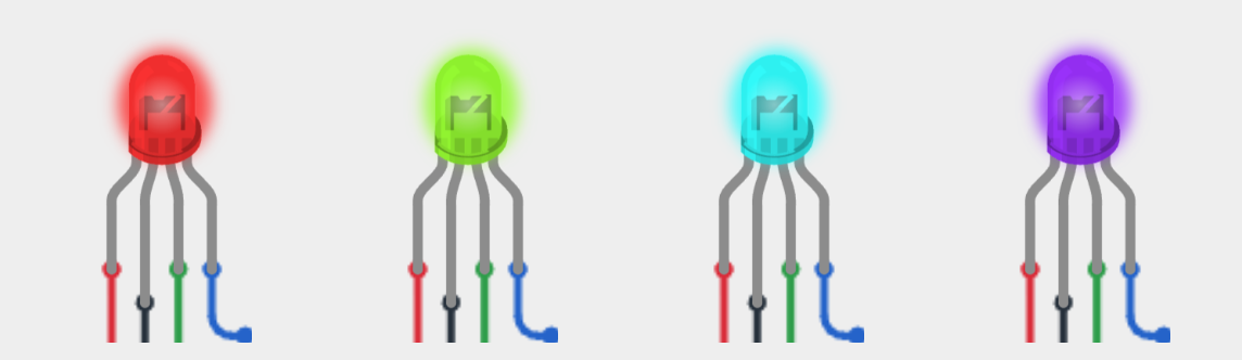
In order, with the knob at the start, a quarter of the way round, halfway and three quarters: red (hue=0 R=255 G=0 B=0), yellow-green (hue=90 R=126 G=255 B=0), cyan (hue=179 R=0 G=255 B=255) and violet (hue=271 R=133 G=0 B=255). On real hardware the readings vary a little. Device Serialhue=179 R=0 G=255 B=255hue=90 R=126 G=255 B=0hue=359 R=255 G=0 B=0hue=0 R=255 G=0 B=0OutputSerial Monitorhue=179 R=0 G=255 B=255hue=90 R=126 G=255 B=0hue=359 R=255 G=0 B=0hue=0 R=255 G=0 B=0Not working? See troubleshooting.

Troubleshooting
Find your symptom; the checks under it run from the most common cause down.
Nothing lights, but the Serial Monitor shows readings
The sketch runs, but no current flows through the LED. Check, in order:
- The longest lead goes to GND. On a common-cathode LED that is the shared lead; with it unwired, no colour has a way back.
- The colour leads go to pins 11, 10 and 9. Red, green and blue each go through their own resistor.
- It is a common-cathode LED. A common-anode one stays dark wired this way; see common anode.
The colours are in the wrong places
- The leads are in the order R, −, G, B. Read them with the longest lead second from the left. If your LED's datasheet shows another order, swap the pin numbers in the sketch to match.
The colours are the opposite: cyan where it should be red
- It is a common-anode LED, with its longest lead on 5V. Each colour then lights when its pin is LOW, so every colour comes out as its opposite; see common anode.
One colour never lights or never dims
- Its pin is a PWM pin. On an Uno only 3, 5, 6, 9, 10 and 11 can dim; on others
analogWrite()switches fully off below 128 and fully on from 128. - Its resistor joins its lead to its pin. Each colour lead needs its own resistor, from the lead to that colour's pin.
Nothing in the Serial Monitor, or garbled characters
- The Serial Monitor is set to 115200 baud. It must match
Serial.begin(115200)in the sketch. - The sketch prints only when the hue changes. It prints once at the start; turn the knob to see more.
Make it yours
- One fixed colour: send three levels of your choice.
- A slow rainbow on its own: step the hue by 1 every 20 ms instead of reading the knob.
// One fixed colour: magenta, red and blue at full.
void setColour(int red, int green, int blue) {
  analogWrite(RED_PIN, red);
  analogWrite(GREEN_PIN, green);
  analogWrite(BLUE_PIN, blue);
}

// in loop(), instead of the knob:
setColour(255, 0, 255);// Once round the wheel in about 7 seconds.
static int hue = 0;
showHue(hue);
hue = (hue + 1) % 360;
delay(20);Common anode
The other kind of RGB LED shares its anode instead: the longest lead goes to 5V, and each colour lights when its pin goes LOW. Wire it the same way otherwise, and send 255 minus each level:
// Common anode: the shared lead to 5V, and each colour
// lights when its pin goes LOW, so send 255 minus the level.
analogWrite(RED_PIN, 255 - red);
analogWrite(GREEN_PIN, 255 - green);
analogWrite(BLUE_PIN, 255 - blue);
FAQ
Is my RGB LED common cathode or common anode?
The listing or the datasheet says. To test it, put the longest lead to GND and one other lead through a 220 Ω resistor to 5V: if it lights, it is common cathode; if not, try the longest lead to 5V and the other through the resistor to GND.
Do I need three resistors?
Yes, one for each colour: each is its own LED, and each needs its own limit. 220 Ω from 5 V keeps each under its 20 mA limit.
Does an RGB LED work on an ESP32?
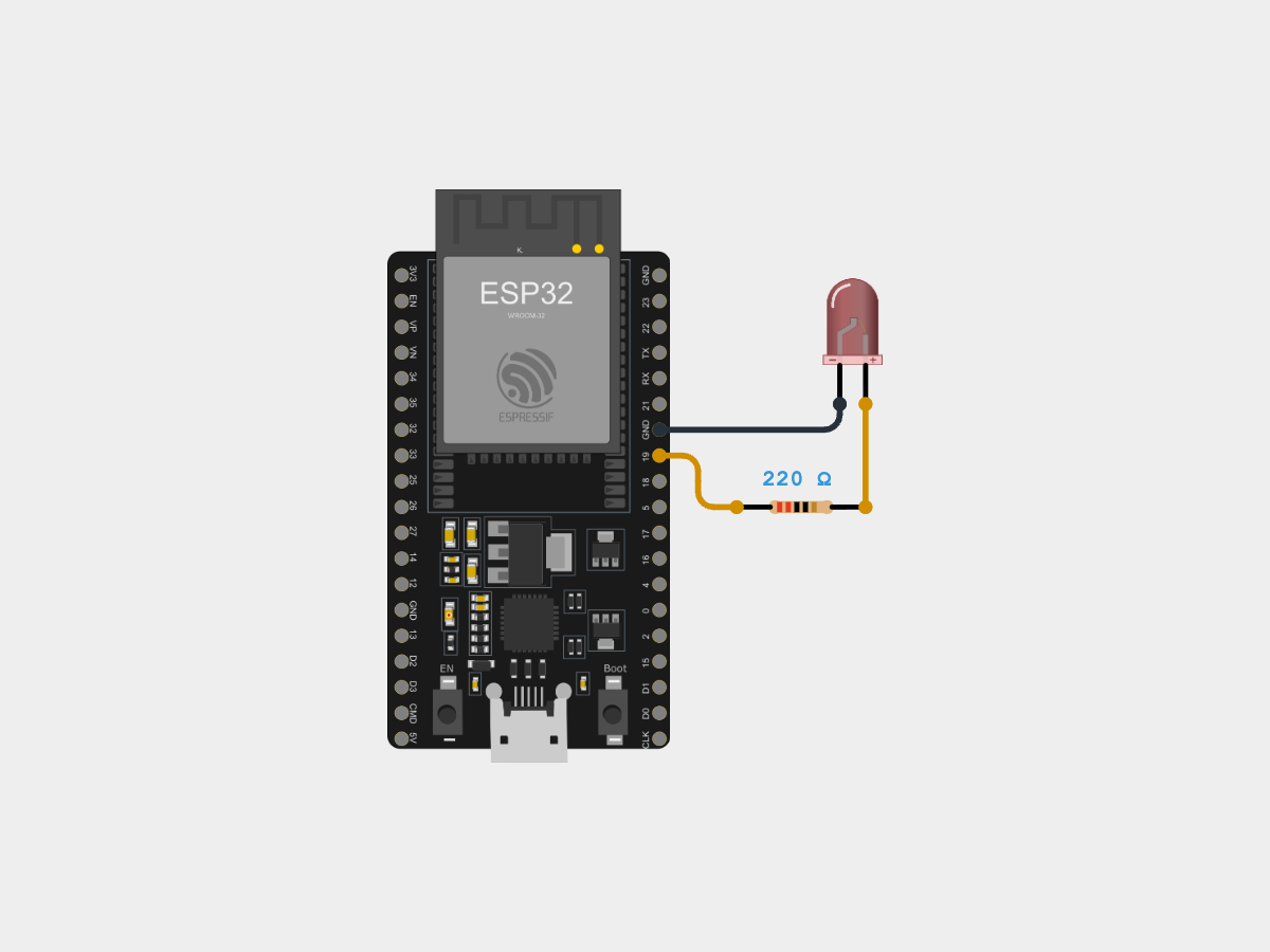
Red does, but green and blue need about 3.2 V and an ESP32 pin gives 3.3 V, so they may be dim or dark. For full colour, drive it from 5 V through transistors.
Simulating the RGB LED in Cirkit Designer
Cirkit's RGB LED lights each colour while its lead is at least that colour's typical forward voltage above the cathode (red 1.8 V, green and blue 3.2 V) and the cathode is wired. Each colour's brightness is the share of time it is lit, so PWM mixes colours as on a real LED. It is tested on the Arduino Uno and the ESP32-S3.
Where it differs from a real LED: Cirkit works with voltages, not current, so a lit colour is always full brightness whatever the resistor, and a missing resistor isn't caught. In Cirkit Designer, the RGB LED's panel warns when a colour is driven below its maximum forward voltage, as green and blue are on a 3.3 V board; a real LED may be dim there.
References
- Fedy FD-5WSRGB-A, 5 mm RGB LED: datasheet (common anode and cathode, forward voltages, 20 mA)
- Arduino: analogWrite() (PWM pins, 0 to 255)
- Arduino AVR core 1.8.6: analogWrite() on a pin without PWM
- SparkFun: light-emitting diodes (polarity, why the resistor)
- Arduino Nano (the same ATmega328P and pins as the Uno)
- SparkFun: resistors (the colour code)
- Arduino: AnalogReadSerial (the potentiometer on A0, read as 0 to 1023)
- Arduino IDE 2: uploading a sketch (the board menu, Upload, the Serial Monitor)