
Dim an LED with a Knob on an Arduino
 By Austin SmallUpdated November 11, 2026
Turn a knob and an LED follows it, from off to full brightness. The Arduino reads the knob with analogRead() and sets the brightness with analogWrite().
This builds on blinking an LED: the same LED and resistor on pin 9, plus a knob on A0. If you haven't wired an LED before, start there. On an ESP32, see dim it on an ESP32.
Try it first, no parts needed
This is the whole project, wired and running in your browser. Press Run simulation, then turn the knob and watch the LED follow it.

The knob on A0
Turning the knob from end to end takes the LED from off to full brightness.
The LED
Its glow, enlarged.
Lights up when the simulation runs.
Arduino Uno serial monitor115200 baud
What the code does
The sketch reads the knob, turns its position into a brightness, and sets the LED to it, over and over.
// Turn the knob on A0: the LED on pin 9 follows it,
// from off to full brightness.
const int KNOB_PIN = A0;
const int LED_PIN = 9;  // a PWM pin: marked ~ on the Uno

int shownLevel = -1;

void setup() {
  Serial.begin(115200);
  pinMode(LED_PIN, OUTPUT);
}

void loop() {
  int reading = analogRead(KNOB_PIN);  // 0 to 1023
  int level = map(reading, 0, 1023, 0, 255);
  analogWrite(LED_PIN, level);  // 0 off, 255 full

  // Print only when the level changes.
  if (level != shownLevel) {
    shownLevel = level;
    Serial.print(F("A0="));
    Serial.print(reading);
    Serial.print(F(" PWM="));
    Serial.println(level);
  }
  delay(10);
}const int LED_PIN = 9; // a PWM pin: marked ~ on the UnoOnly some pins can dim an LED: on an Uno, 3, 5, 6, 9, 10 and 11, marked with a ~ on the board. Pin 9 is one.
int reading = analogRead(KNOB_PIN); // 0 to 1023Reads the knob: 0 at one end, 1023 at the other.
int level = map(reading, 0, 1023, 0, 255);Scales that to 0 to 255, the range
analogWrite()takes.analogWrite(LED_PIN, level); // 0 off, 255 fullSets the brightness: 0 keeps the LED off, 255 keeps it fully on, and in between it is on for that share of each pulse.
if (level != shownLevel) {
  shownLevel = level;
  Serial.print(F("A0="));
  Serial.print(reading);
  Serial.print(F(" PWM="));
  Serial.println(level);
}
Prints only when the level changes, so the Serial Monitor isn't flooded.
How it works
Each time round the loop, the knob sets a voltage on A0, and PWM turns the number it becomes into brightness.
How the knob reads
The knob is a potentiometer. Its outer legs go to 5V and GND, and its middle leg, the wiper, to A0. Turning it moves the wiper's voltage from 0 V at one end to 5 V at the other, and analogRead() reads that as 0 to 1023.

How the LED dims: PWM
An Uno pin is only ever at 0 V or 5 V, so it can't give an LED a little less voltage. Instead, analogWrite() switches pin 9 on and off 490 times a second and leaves it on for the share of each pulse you ask for. Your eye averages the flicker, so the LED looks steadily dimmer.
On for 50% of each pulse
HIGH lights the LED; LOW leaves it dark.
On the Uno's pin 9 the pulses come 490 times a second (pins 5 and 6: 980).
Build it
Three steps with real parts: wire it, get the code, then upload it and turn the knob.
You'll need
- An Arduino Uno (a Nano works the same way) and its USB cable
- A red LED, 5 mm or 3 mm, and a 220 Ω resistor (red, red, brown bands)
- A 10 kΩ potentiometer, the knob
- A breadboard and five jumper wires
- Software to upload the sketch to the Uno: either Cirkit Designer, free in your browser, or the Arduino IDE, a free download for Windows, macOS and Linux
Wire it
The LED and its resistor from pin 9 to GND, as for Blink, then three wires for the knob. Not sure which leg is which? See the LED pinout.
Tap a connection to see it on the circuit.
Pin Connect to the Uno Show LED anode (long leg) 220 Ω resistor, then pin 9 Show LED cathode (short leg) GND Show Knob, one outer leg 5V Show Knob, middle leg A0 Show Knob, other outer leg GND Show The LED must be on a PWM pin, marked ~ on the board. On any other pin it only switches on and off.
Get the code
I'm using:Steps 2 and 3 follow the tool you pick.
The project opens with the sketch already in it, so there's nothing to install.
No Arduino IDE yet? Download it free for Windows, macOS or Linux.
The sketch needs no library. Copy it into a new sketch:
How it works line by line is in what the code does, above.
Upload and check it
Plug in your Uno. In Cirkit, open the Build tab, then Upload firmware: click Select Port and pick your Uno, then Upload to Device. The first time, Cirkit asks you to install Cirkit Create Agent, a small desktop helper that lets it reach the board over USB. Then open Upload output and serial monitor and click Start Serial Monitor.
Show me where to click in Cirkit
 LED dimmed with a knobDesignCodeSimulateBuildShare
Select a device port
Select the device port for uploading code and serial communications
COM3 (Arduino Uno)- Open Build
- Choose Upload firmware
- Click Select Port
- Pick COM3 (Arduino Uno)
- Click Upload to Device
- Open Upload output and serial monitor
- Click Start Serial Monitor
In the Arduino IDE, choose Arduino Uno and its port from the board menu, press Upload, then open the Serial Monitor and set it to 115200 baud.
Show me where to click in the Arduino IDE
led_knob.ino// Turn the knob on A0: the LED on pin 9 follows it, // from off to full brightness. const int KNOB_PIN = A0; const int LED_PIN = 9; // a PWM pin: marked ~ on the Uno int shownLevel = -1;
OutputSerial Monitor115200 baudCompiling sketch...
Sketch uses 2670 bytes (8%) of program storage space. Maximum is 32256 bytes.
Global variables use 190 bytes (9%) of dynamic memory, leaving 1858 bytes for local variables. Maximum is 2048 bytes.
Uploading...
A0=512 PWM=127
A0=257 PWM=64
A0=1023 PWM=255
A0=0 PWM=0
Done uploading.
- Click the board menu
- Pick Arduino Uno on COM3
- Click Upload
- Wait for Done uploading
- Click Serial Monitor
- Check it is set to 115200 baud
It works when:
- Turning the knob from one end to the other takes the LED from off to full brightness.
- The Serial Monitor prints a line each time the level changes, such as
A0=512 PWM=127with the knob in the middle.
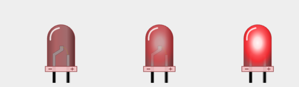
Left to right: off with the knob at the start (A0=0 PWM=0), dim a quarter of the way round (A0=257 PWM=64), and full with it turned all the way (A0=1023 PWM=255). On real hardware the readings vary a little. Device SerialA0=512 PWM=127A0=257 PWM=64A0=1023 PWM=255A0=0 PWM=0OutputSerial MonitorA0=512 PWM=127A0=257 PWM=64A0=1023 PWM=255A0=0 PWM=0Not working? See troubleshooting.

Dim it on an ESP32
The same dimmer runs on an ESP32 DevKitC, the common ESP32-WROOM-32 board. The LED moves to GPIO 19 and the knob to GPIO 34, and the knob's outer leg goes to 3V3, not 5V. The sketch reads the knob in millivolts and dims the LED with the ESP32's LED controller, LEDC. New to the ESP32? Blink an LED on one first; that guide covers installing the board and uploading to it.
Wire it
Tap a connection to see it on the circuit.
| Pin | Connect to the ESP32 | Show |
|---|---|---|
| LED anode (long leg) | 220 Ω resistor, then GPIO 19 | Show |
| LED cathode (short leg) | GND | Show |
| Knob, one outer leg | 3V3 | Show |
| Knob, middle leg | GPIO 34 | Show |
| Knob, other outer leg | GND | Show |
Keep the knob on 3V3. GPIO 34 isn't 5 V tolerant. Put the knob on an ADC1 pin, GPIO 32 to 39 (on the DevKitC's headers, 32 to 35, VP and VN), so it still reads if you add Wi-Fi later. For the LED's pin, see which ESP32 pins can drive it.
What the ESP32 sketch does
It reads the knob in millivolts, turns that into a level from 0 to 255, and sets the LED to it with LEDC.
// Turn the knob on GPIO 34: the LED on GPIO 19 follows
// it, from off to full brightness.

// GPIO 34 is on ADC1, which still reads while Wi-Fi runs.
const int KNOB_PIN = 34;
const int LED_PIN = 19;
const int PWM_FREQUENCY = 5000;  // Hz
const int PWM_BITS = 8;          // duty from 0 to 255

int shownLevel = -1;

void setup() {
  Serial.begin(115200);
  ledcAttach(LED_PIN, PWM_FREQUENCY, PWM_BITS);
}

void loop() {
  // Millivolts, corrected with the chip's calibration.
  // The input's measurable range is about 150 to 3100 mV,
  // so that span is the LED's whole range.
  int millivolts = analogReadMilliVolts(KNOB_PIN);
  int clamped = constrain(millivolts, 150, 3100);
  int level = map(clamped, 150, 3100, 0, 255);
  ledcWrite(LED_PIN, level);  // 0 off, 255 full

  // Print only when the level changes.
  if (level != shownLevel) {
    shownLevel = level;
    Serial.print(F("IO34 "));
    Serial.print(millivolts);
    Serial.print(F(" mV PWM="));
    Serial.println(level);
  }
  delay(10);
}const int KNOB_PIN = 34;The knob on GPIO 34, an ADC1 pin.
const int LED_PIN = 19;The LED on GPIO 19; most ESP32 pins can drive one.
ledcAttach(LED_PIN, PWM_FREQUENCY, PWM_BITS);Sets GPIO 19 up for PWM: 5,000 pulses a second, with levels from 0 to 255, as on an Arduino.
int millivolts = analogReadMilliVolts(KNOB_PIN);Reads the knob in millivolts; why millivolts is below.
int level = map(clamped, 150, 3100, 0, 255);constrain()andmap()turn the reading into a level from 0 to 255; reading the knob in millivolts says why the range is 150 to 3,100.ledcWrite(LED_PIN, level); // 0 off, 255 fullSets the LED's brightness, keeping it on for that share of each pulse.
Open the ESP32 dimmer in Cirkit Designer
Or copy it into the Arduino IDE, with the ESP32 boards installed (esp32 by Espressif, version 3.0 or later):
Reading the knob in millivolts
The ESP32's analog input gives a count from 0 to 4095, but the count isn't proportional to the voltage. At the Arduino core's default setting (11 dB of attenuation), the classic ESP32 measures only from about 150 mV to 3,100 mV. So the sketch reads millivolts with analogReadMilliVolts(), which corrects the count with the chip's calibration. Mapping that span to 0 to 255 lets the knob's whole travel take the LED from off to full.
How LEDC dims the LED
LEDC makes the same pulses as analogWrite() on an Uno (see how the LED dims), between 0 V and 3.3 V. Unlike on an Uno, you choose their speed and resolution. ledcAttach(pin, frequency, bits) takes up to 20 bits on a classic ESP32 and 14 on the ESP32-S3. The sketch asks for 5,000 pulses a second and 8 bits, so levels run from 0 to 255 as on an Uno.
analogWrite() works too, from 0 to 255 as on an Uno. Drop the ledcAttach() line and use it in place of ledcWrite(); it sets the pin up with LEDC itself, at 1,000 pulses a second.
// The same brightness with analogWrite(): 0 to 255, no ledcAttach().
analogWrite(LED_PIN, level);
Upload and check it
Upload it as in the ESP32 Blink guide (in the Arduino IDE, choose ESP32 Dev Module), then open the Serial Monitor at 115200 baud.
It works when:
- Turning the knob from one end to the other takes the LED from off to full brightness.
- After a few start-up lines from the ESP32's boot ROM, the Serial Monitor prints a line each time the level changes, such as
IO34 1660 mV PWM=130with the knob in the middle.

On an ESP32-S3
Move two pins. GPIO 19 is the S3's USB D− pin, so put the LED on another, such as GPIO 4, and set LED_PIN to 4. Put the knob on an ADC1 pin, such as GPIO 1, and set KNOB_PIN to 1. The S3's input measures from 0 mV, so change 150 to 0 in the two lines that clamp and map the reading. In the Arduino IDE, choose ESP32S3 Dev Module.
Troubleshooting
Find your symptom; the checks under it run from the most common cause down.
The LED doesn't follow the knob, or the reading jumps about
Watch the Serial Monitor's reading as you turn the knob. Check, in order:
- The knob's middle leg is on A0, or GPIO 34 on an ESP32. With nothing on that pin, its reading wanders on its own.
- Its outer legs go one to 5V, one to GND, or 3V3 and GND on an ESP32. Both on the same pin, the reading stays put wherever the knob is.
- The reading runs from end to end, 0 to 1023 on an Uno and about 150 to 3,100 mV on an ESP32. If it does and the LED still doesn't change, see the LED never lights.
The LED only switches on and off; it won't dim
- The LED is on a PWM pin. On an Uno only 3, 5, 6, 9, 10 and 11 can dim it. On any other pin,
analogWrite()switches it off below 128 and fully on from 128.
The LED never lights, but the readings change
- The LED is the right way round. Its long leg goes toward the resistor. The LED guide's troubleshooting has the other checks.
Nothing in the Serial Monitor, or garbled characters
- The Serial Monitor is set to 115200 baud. It must match
Serial.begin(115200)in the sketch. - The sketch prints only when the level changes. It prints once at the start; turn the knob to see more.
On an ESP32, compiling fails: 'ledcAttach' was not declared in this scope, or 'ledcSetup' was not declared
'ledcAttach' was not declared in this scope, or 'ledcSetup' was not declared- The ESP32 boards are version 3.0 or later. The ESP32 sketch uses
ledcAttach(), which version 3.0 added: update esp32 by Espressif in the Boards Manager. - Older code is rewritten for 3.x. Version 3.0 removed
ledcSetup()andledcAttachPin()for oneledcAttach(), andledcWrite()now takes the pin, not a channel:
// ESP32 core 2.x: a channel set up, then a pin attached to it.
ledcSetup(0, 5000, 8);
ledcAttachPin(LED_PIN, 0);
ledcWrite(0, level);

// ESP32 core 3.x: one call, then write to the pin.
ledcAttach(LED_PIN, 5000, 8);
ledcWrite(LED_PIN, level);
Make it yours
- Turn it the other way: swap the knob's outer legs, or write
map(reading, 0, 1023, 255, 0). - Another pin: set
LED_PINto 3, 5, 6, 10 or 11, the Uno's other PWM pins, and move the wire. - Fade on its own: step the level up and down instead of reading the knob. Fifty-one steps of 5, 50 ms apart, take about 2.6 s each way.
// Fade up and down on its own, about 2.6 s each way.
const int LED_PIN = 9;
int level = 0;
int step = 5;

void setup() {
  // Nothing to set up: analogWrite() makes the pin an output itself.
}

void loop() {
  analogWrite(LED_PIN, level);
  level = level + step;
  if (level <= 0 || level >= 255) {
    step = -step;  // turn round at either end
  }
  delay(50);
}FAQ
What is PWM?
Pulse-width modulation: switching a pin fully on and off, too fast to see, and setting the share of each pulse it's on. analogWrite() does it on the Uno's PWM pins, 490 times a second on pin 9. See how the LED dims.
Why doesn't analogWrite() dim my LED?
It's on a pin without PWM. On an Uno, use 3, 5, 6, 9, 10 or 11. See it won't dim.
What potentiometer do I need?
A 10 kΩ one, as Arduino's own examples use. On an Uno its outer legs go to 5V and GND and its middle one to A0; on an ESP32, to 3V3, GND and GPIO 34. See how the knob reads.
Do I need pinMode() for analogWrite()?
No: analogWrite() sets the pin as an output itself. This sketch calls pinMode() anyway, which does no harm.
Does analogWrite() work on an ESP32?
Yes, in the ESP32 core 3.x. See how LEDC dims the LED for when to use it and when to use ledcWrite().
Simulating the dimmer in Cirkit Designer
Cirkit's red LED lights while its anode is at least 2 V above its cathode, measures the share of each PWM pulse it's lit, and updates its brightness every 20 ms, so analogWrite() shows as a steady partial brightness, as on a real LED. It is tested on the Arduino Uno, the ESP32-S3 and the classic ESP32. The ESP32's analog input follows Espressif's default calibration curve. The knob adds no noise, so its readings don't wobble the way a real one's can.
Where it differs from a real LED: Cirkit works with voltages, not current, so the resistor's value doesn't change the brightness. On real hardware, always fit the resistor.
References
- Arduino: analogWrite() (PWM pins, 490 and 980 Hz, 0 to 255, no pinMode needed)
- Arduino: analogRead() (0 to 1023; an unconnected pin's reading fluctuates)
- Arduino: PWM (switching a pin on and off fast, the share of time on)
- Arduino: Fade
- Arduino IDE 2: uploading a sketch (the board menu, Upload, the Serial Monitor)
- Arduino: AnalogReadSerial (the potentiometer's legs, 0 to 5 V on the wiper, read as 0 to 1023)
- Arduino: AnalogInOutSerial (a potentiometer setting an LED's brightness)
- Arduino AVR core 1.8.6: analogWrite() on a pin without PWM
- Arduino-ESP32: LEDC (ledcAttach(), ledcWrite(), resolution, analogWrite())
- Arduino-ESP32: migrating from 2.x to 3.0 (ledcSetup() and ledcAttachPin() removed)
- Arduino-ESP32 core, version 3.3.5 (the ADC's default 11 dB attenuation)
- Arduino-ESP32: ADC, including analogReadMilliVolts() and the measurable range
- ESP-IDF: ADC on the ESP32, and ADC2 shared with Wi-Fi
- Arduino-ESP32 core 3.3.5: esp32-hal-ledc.c (analogWrite() at 1,000 Hz, 8 bits, by default)
- Espressif ESP32 datasheet (ADC1 pins, input voltage limits)
- Espressif ESP32-DevKitC user guide (ADC1 on its headers)
- Espressif ESP32-S3 datasheet (GPIO 19 and 20 as USB D− and D+)